
Pinless accumulator piston

a technology of accumulator pins and pistons, applied in mechanical devices, clutches, couplings, etc., can solve the problems of poor shift quality, damaged clutches and bands, wear at the accumulator pin/piston interface, etc., and is not practical for the present application

Active Publication Date: 2005-02-17
SONNAX TRANSMISSION CO
View PDF6 Cites 16 Cited by
  • Summary
  • Abstract
  • Description
  • Claims
  • Application Information

AI Technical Summary

Benefits of technology

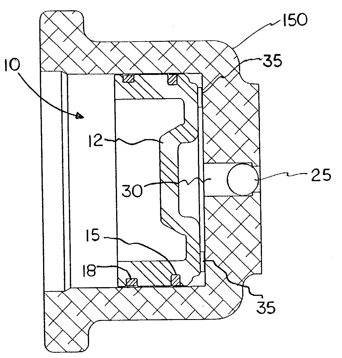
[0013] Accordingly, the present invention is a replacement pinless accumulator piston for the GM transmissions having an axial length substantially less than the piston diameter and which eliminates the accumulator pin thereby resolving the problem of hydraulic leakage at the accumulator pin / piston interface. This modification is facilitated by providing additional seals and / or guide rings about circumference of the piston. The additional seals and / or guide rings guide the reciprocating movement of the piston within the piston bore in the absence of the accumulator pin and serve to maintain the hydraulic integrity of the accumulator.
[0014] The present pinless accumulator piston is a direct replacement for both the forward clutch accumulator, and the 1-2 and 3-4 accumulators in the aforementioned GM transmissions. In addition, the pinless accumulator piston may be fabricated from alternative materials such as steel bar stock, cast aluminum and engineering grade resins such as phenolic resin to reduce manufacturing costs.

Problems solved by technology

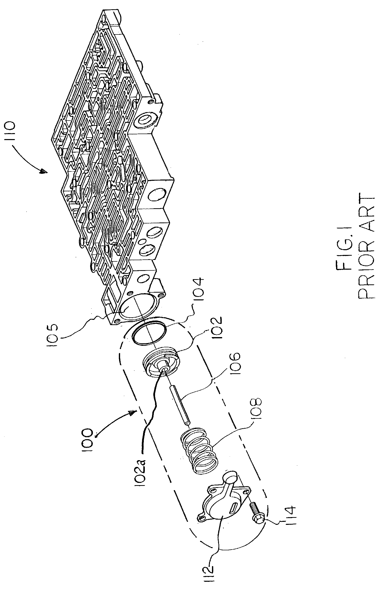
In the original equipment manufacture (hereinafter “OEM”) of the GM transmissions, an aluminum accumulator piston typically reciprocates against spring pressure on a cylindrical steel accumulator pin, which eventually causes wear at the accumulator pin / piston interface.
Such wear causes hydraulic leakage at the accumulator pin / piston interface resulting in poor shift quality and damaged clutches and bands.
U.S. Pat. No. 5,025,823 to Stevenson and U.S. Pat. No. 4,046,162 to Rodeghiero also disclose accumulator pistons having axial length to diameter ratios, which are not practical for the present application.

Method used


Image

  • Pinless accumulator piston
  • Pinless accumulator piston
  • Pinless accumulator piston

Examples


Embodiment Construction

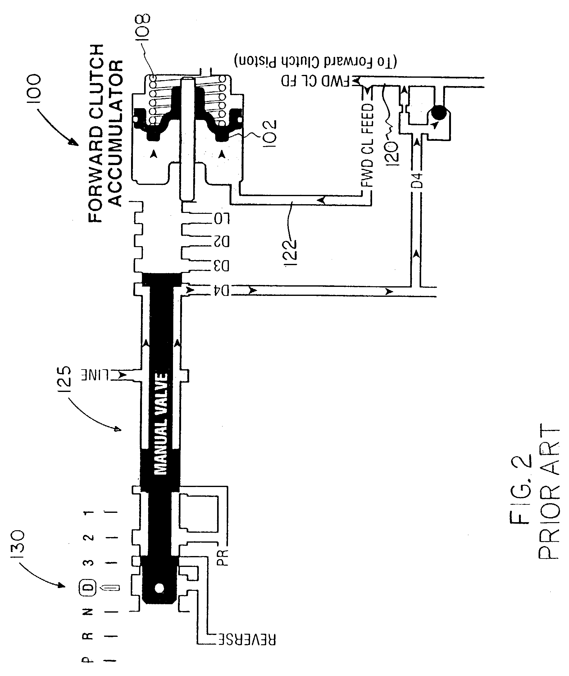
[0025] Prior to describing the present invention in detail it may be beneficial to briefly review the structure and function of the accumulator assemblies of the prior art GM transmissions. It will be understood that a plurality of such accumulator assemblies are typically utilized within a particular transmission and may be integrated into the transmission valve body, mechanically attached to the valve body, or integrated into the transmission case as described hereinafter.

[0026] With reference to the drawings there is shown therein a forward clutch accumulator assembly of the GM 4L60E transmission, indicated generally at 100, in accordance with the prior art and illustrated in FIG. 1. The forward clutch accumulator assembly 100 (enclosed within broken line) is shown in exploded view and removed from its functional position within the piston bore 105, which is machined into the valve body, indicated generally at 110, as shown.

[0027] In the prior art the forward clutch accumulator...


PUM


Abstract

A replacement accumulator piston for various General Motors transmissions, which absorbs clutch apply fluid pressure to cushion the application of a clutch band against fluid shock is disclosed. The present pinless accumulator piston design eliminates the accumulator pin whereon the original equipment accumulator piston resides thereby resolving the problem of hydraulic leakage at the accumulator pin / piston interface. The elimination of the accumulator pin is accomplished by increasing the axial length of the piston sidewall or skirt, which permits the use of additional guide rings about circumference of the piston. The additional guide rings facilitate the reciprocating movement of the piston within the piston bore in the absence of the accumulator pin and also serve to maintain the hydraulic integrity of the accumulator. The pinless accumulator piston is a direct replacement for both the forward clutch accumulator, and the 1-2 gear and 3-4 gear accumulators in General Motors transmissions.

Description

CROSS-REFERENCE TO RELATED APPLICATION [0001] This application claims the benefit under 35 U.S.C. 119(e) of U.S. Provisional Patent Application No. 60 / 359,476 filed Feb. 26, 2002, entitled Improved Accumulator Piston.BACKGROUND OF THE INVENTION [0002] The present invention relates generally to the field of automatic transmission systems and, more particularly, to a pinless accumulator piston for use in General Motors 4L60, 4T60, 4T60E, 4L60E and 4L80E transmissions (hereinafter “GM transmissions”). [0003] Automatic transmission systems of the prior art have a hydraulic circuit sub-system which includes at least a hydraulic pump, a valve body having fluid conducting passages or circuits, input and exhaust ports formed within the fluid circuits, and a plurality of valves comprised of generally cylindrical pistons having control diameters or lands formed thereon, which alternately open and close the ports to the fluid circuits to regulate the flow and pressure of automatic transmission...

Claims


Application Information

Patent Timeline
Patent Type & Authority Applications(United States)
IPC IPC(8): F16D48/02F16H61/06
CPCF16D25/14F16D48/02F16H61/067F16D2048/0215F16D2048/0203F16D2300/22
Inventor CARNE, GARY S.
Owner SONNAX TRANSMISSION CO
Learn More