Hanger rod for drying cabinet

a drying cabinet and hanging rod technology, applied in the direction of hanging devices for fruit, curtain suspension devices, lighting and heating apparatus, etc., to achieve the effect of preventing the rotation of the hanging rod, reducing the risk of color transfer between wet garments, and improving drying efficiency

Inactive Publication Date: 2005-02-17
MAYTAG
View PDF26 Cites 84 Cited by
  • Summary
  • Abstract
  • Description
  • Claims
  • Application Information

AI Technical Summary

Benefits of technology

[0008] The hanger rod of the present invention is adapted for use in a drying cabinet to support hangers with clothes or garments during the drying process. The hanger rod includes an elongated bar having a plurality of notches, each adapted to receive a hanger. Each notch is V-shaped and tapered downwardly to a substantially pointed apex. The bar thickness ranges between 30%-7...

Problems solved by technology

However, with prior art hanger rods, the hangers tend...

Method used


Image

  • Hanger rod for drying cabinet
  • Hanger rod for drying cabinet
  • Hanger rod for drying cabinet

Examples


Embodiment Construction

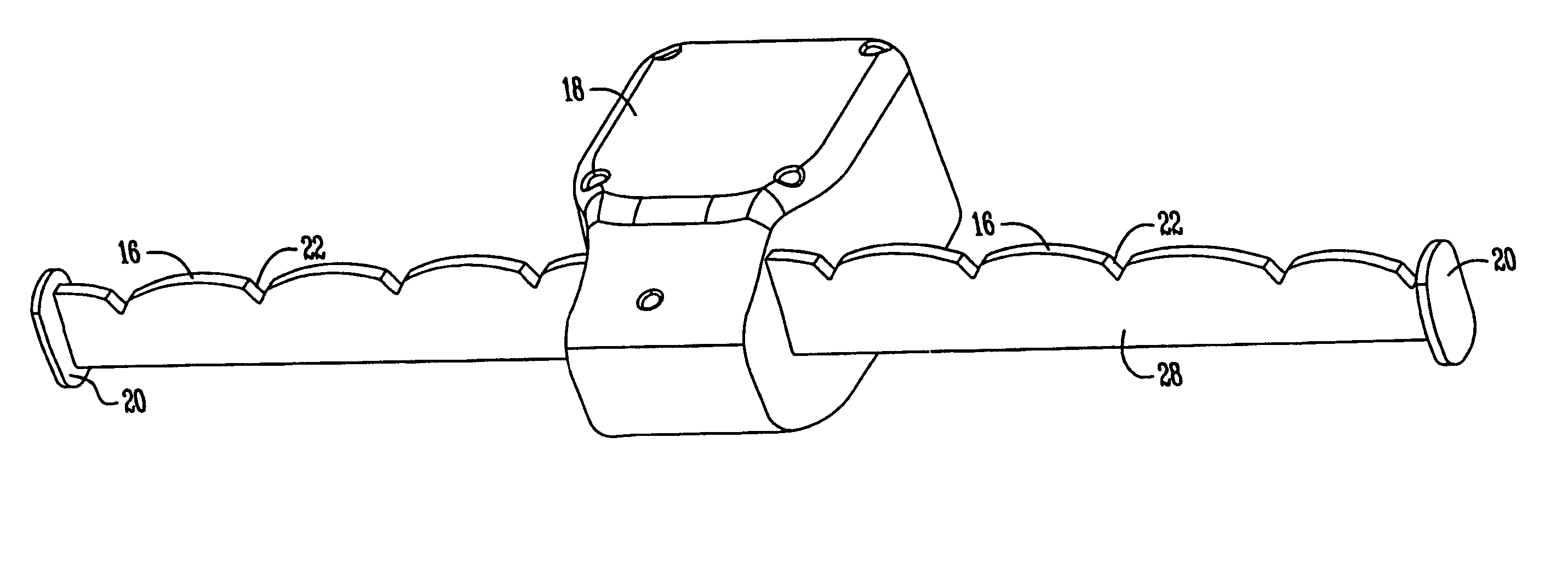
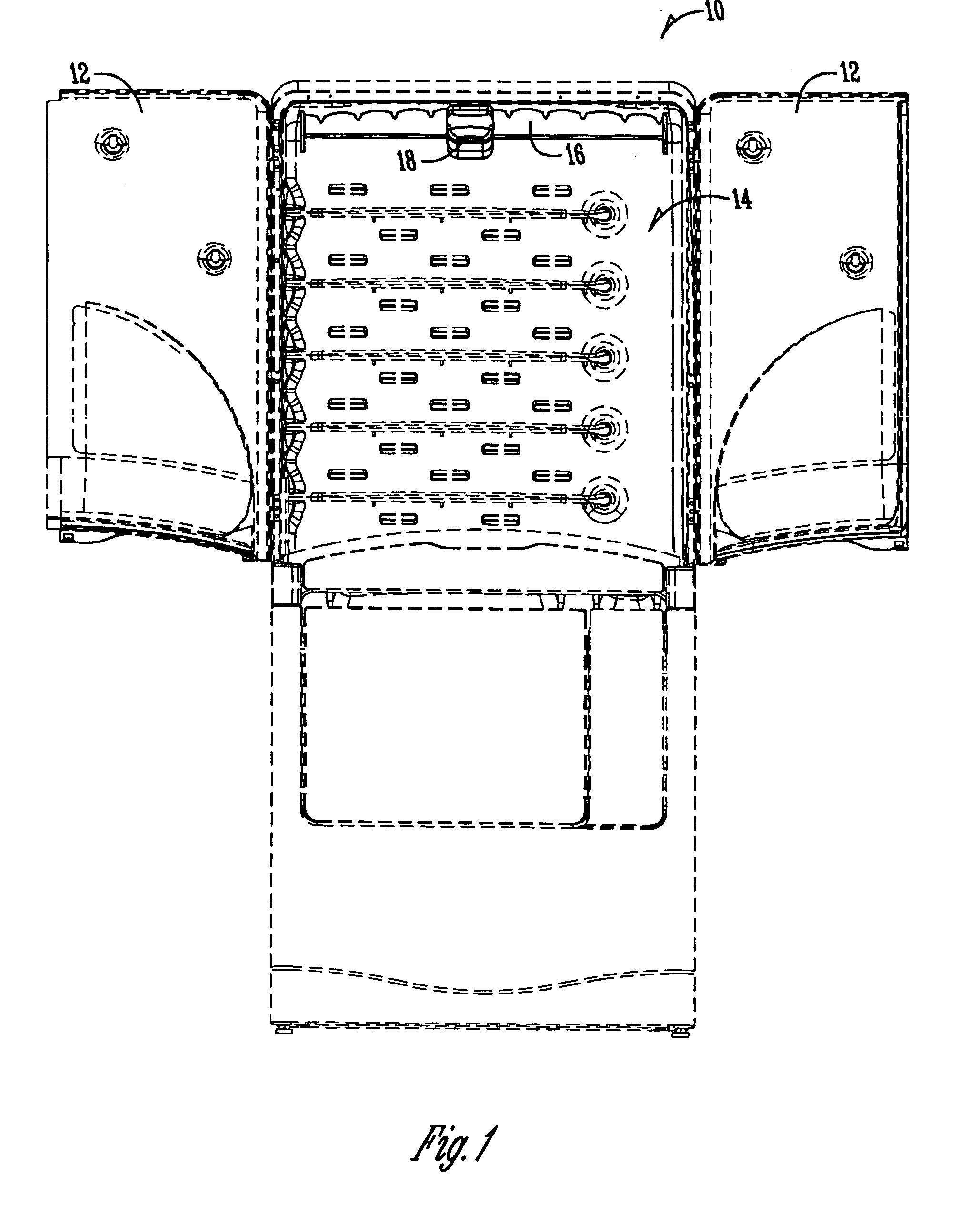
[0015] A clothes drying cabinet is designated by the reference numeral 10 in the drawings. The cabinet 10 includes a pair of upper doors 12 which are movable between open and closed positions to provide access to an internal drying chamber 14. The drying chamber 14 includes a hanger rod 16 mounted therein to support hangers 15 with clothes or garments for drying in the chamber 14. A shaker 18 may be operatively mounted within the internal drying chamber 14 and attached to the hanger rod 16 so as to shake the rod 16 during the drying process to facilitate de-wrinkling of the clothes or garments.

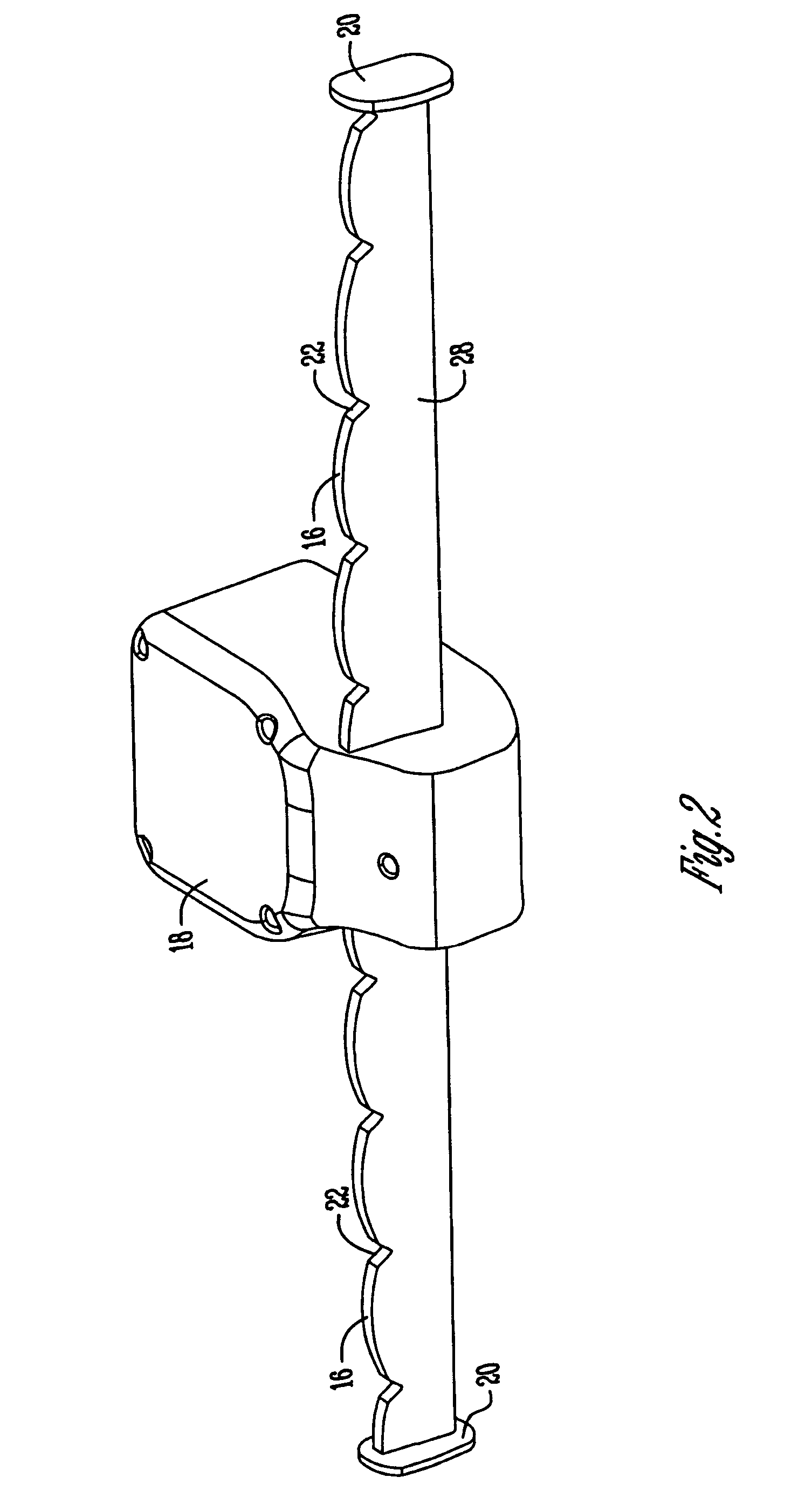
[0016] The present invention is directed towards the hanger rod 16. The rod 16 generally is an elongated bar with opposite ends 20 which are mounted in the drying chamber 14 in any convenient manner. The hanger rod or bar 16 includes a plurality of notches 22 spaced along the length of the rod 16. The notches 22 are each adapted to receive the hanger 15. The hangers 15 may be any commercially...


PUM


Abstract

A hanger rod is provided for a clothes drying cabinet. The rod includes a plurality of notches, each adapted to receive a hanger. Each notch is V-shaped, with opposite side walls which converge downwardly to a substantially pointed apex. The rod has front and rear walls defining a thickness ranging between 30%-75% of the hanger hook diameter. The notches provide four contact points on the hanger hook to prevent rotation of the hanger hook on the rod during the drying process.

Description

BACKGROUND OF THE INVENTION [0001] Hanger rods are well known for use in closets for receiving hangers with clothes. Hanger rods have also been provided in clothes drying cabinets to hang clothes during the drying process. Some prior art rods are provided with notches to maintain spacing between the hangers. In a drying cabinet, it is desirable to shake hanging clothes during the drying process to facilitate de-wrinkling of the clothes. However, with prior art hanger rods, the hangers tend to twist, which allows the clothes to contact one another. Such contact between the clothes decreases drying efficiencies and creates possibilities of dye transfer between the wet clothes. [0002] Therefore, a primary objective of the present invention is the provision of an improved hanger rod for a clothes drying cabinet. [0003] Another objective of the present invention is the provision of a hanger rod which prevents twisting or swiveling of the hangers when the rod is shaken. [0004] A further o...

Claims


Application Information

Patent Timeline
IPC IPC(8): A47B61/00A47G25/06D06F58/10
CPCA47B61/003D06F58/10A47G25/0692
Inventor SCHOBER, STEPHEN D.TREMEL, CURTIS J.
Owner MAYTAG
Why Eureka
Try Eureka