Brushless dc motor having a speed control circuit

Inactive Publication Date: 2005-02-17
SUNONWEALTH ELECTRIC MACHINE IND
View PDF10 Cites 6 Cited by
  • Summary
  • Abstract
  • Description
  • Claims
  • Application Information

AI Technical Summary

Benefits of technology

[0012] The primary objective of this invention is to provide a brushless dc motor having a speed control circuit, which includes a fan motor drive circuit serially connected with an over-current detective/current-limiting circuit and a multi-functional speed control circuit. The multi-functional speed control circuit generates signals to control the over-current detective/current-limiting circuit, thereby controlling the fan motor drive circuit in multiple speed stages.
[0013] The secondary objective of this invention is to provide the brushless dc motor having a speed control circuit, which includes a fan motor drive circuit serially connected with an over-current detective/current-limiting circuit and a multi-functional speed control circuit. The entire circuitry structure of the speed control circuit is simplified by incorporating the multi-functional speed control circuit into the fan motor drive circuit.
[0014] The brushless dc motor in accordance with the present inve

Problems solved by technology

Detecting an over-current, the over-current-detecting / current-limiting circuit controls a current at a low voltage level for passing through the fan motor drive circuit and inadequate to destroy it.

Method used


Image

  • Brushless dc motor having a speed control circuit
  • Brushless dc motor having a speed control circuit
  • Brushless dc motor having a speed control circuit

Examples


Embodiment Construction

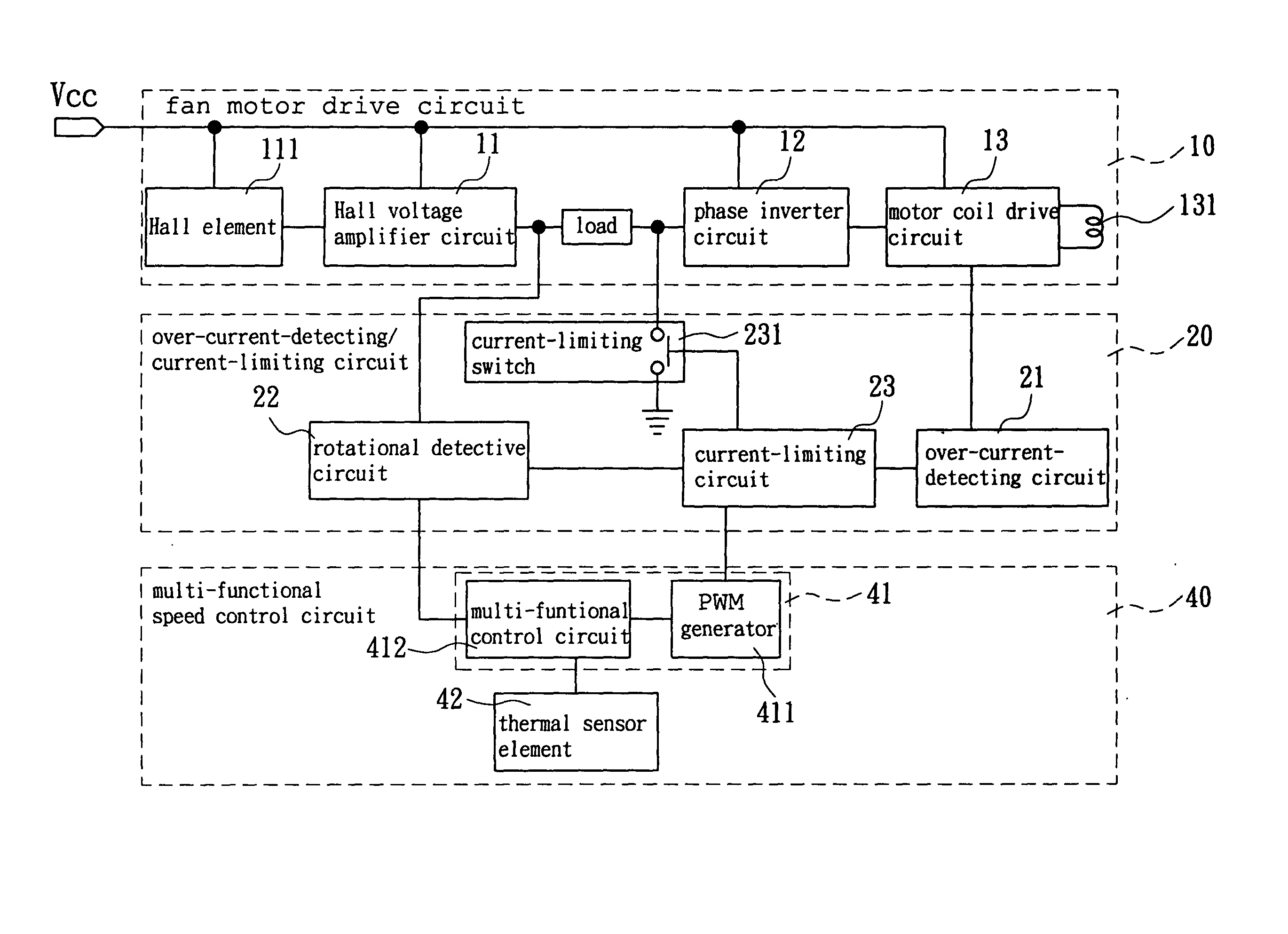
[0023]FIG. 4 illustrates a schematic block diagram of a brushless dc motor having a speed control circuit in accordance with a preferred embodiment of the present invention. Referring to FIG. 4, reference numerals of the first embodiment has applied the identical numerals of the conventional brushless dc motor. The brushless dc motor of the first embodiment has the similar configuration and same function as that of the conventional brushless dc motor and the detailed descriptions are omitted.

[0024] Referring again to FIG. 4, the brushless dc motor in accordance with the present invention includes a fan motor drive circuit 10, an over-current-detecting / current-limiting circuit 20 and a multi-functional speed control circuit 40. The fan motor drive circuit 10 is connected to the over-current-detecting / current-limiting circuit 20 which is further connected to the multi-functional speed control circuit 40. Consequently, the over-current-detecting / current-limiting circuit 20 is connecte...


PUM


Abstract

A brushless dc motor includes a fan motor drive circuit, an over-current-detecting / current-limiting circuit and a multi-functional speed control circuit. The fan motor drive circuit is connected to the over-current-detecting / current-limiting circuit which is further connected to the multi-functional speed control circuit. The over-current-detecting / current-limiting circuit is adapted to detect a rotational speed and an over-current. Detecting an over-current, the over-current-detecting / current-limiting circuit controls a current at a low voltage level for passing through the fan motor drive circuit and inadequate to destroy it. The multi-functional speed control circuit sends a predetermined speed signal to control the over-current-detecting / current-limiting circuit for carrying out speed control of the brushless dc motor.

Description

BACKGROUND OF THE INVENTION [0001] 1. Field of the Invention [0002] The present invention is related to a brushless dc motor having a speed control circuit. More particularly, the present invention is related to a speed control circuit incorporating into a brushless dc motor, and connecting to a current limiting circuit suitable for controlling rotational speed of the brushless dc motor. [0003] 2. Description of the Related Art [0004] Referring to FIG. 1, it illustrates a schematic block diagram of a dual current-limiting circuit for a brushless dc fan motor. The brushless dc fan motor includes a fan motor drive circuit 10 and a dual current-limiting circuit 20. [0005] The fan motor drive circuit 10 includes a Hall voltage amplifier circuit 11, a phase inverter circuit 12, and a motor coil drive circuit 13. The Hall voltage amplifier circuit 11 is used to amplify a weak Hall voltage and outputted it to the phase inverter circuit 12. The phase inverter circuit 12 inverts the phase of...

Claims


Application Information

Patent Timeline
IPC IPC(8): H02P7/00H02P29/02
CPCH02P29/02
Inventor HORNG, ALEXHONG, CHING-SHENGKO, TA-LUN
Owner SUNONWEALTH ELECTRIC MACHINE IND
Why Eureka
Try Eureka