Display driver circuit

Active Publication Date: 2021-09-16
SHENZHEN CHINA STAR OPTOELECTRONICS SEMICON DISPLAY TECH CO LTD
View PDF0 Cites 0 Cited by
  • Summary
  • Abstract
  • Description
  • Claims
  • Application Information

AI Technical Summary

Benefits of technology

The present patent application provides a display driving circuit that can output both positive and negative pulse signals simultaneously. The circuit is made up of n-type transistors, which can be manufactured using the same process as the display circuit. This simplifies the circuit structure and improves manufacturing efficiency compared to previous designs that used separate driving circuits for positive and negative pulses. Overall, this invention simplifies the display driving circuit and improves manufacturing efficiency.

Problems solved by technology

In the prior art, the display driving circuit for providing the positive pulse signal and the negative pulse signal to the compensation circuit needs to include both the n-type transistor and the p-type transistor, and in the manufacturing of the array substrate, it is difficult to simultaneously fabricate the driving circuit including the n-type transistor and the driving circuit including the p-type transistor, which involves a complicated process with a low production efficiency.

Method used


Image

  • Display driver circuit
  • Display driver circuit
  • Display driver circuit

Examples


Embodiment Construction

[0039]The following description of the various embodiments is provided to illustrate the specific embodiments of the invention. The spatially relative directional terms mentioned in the present invention, such as “upper”, “lower”, “before”, “after”, “left”, “right”, “inside”, “outside”, “side”, etc. and the like, may be used herein for ease of description to describe one element or feature's relationship to another element(s) or feature(s) as illustrated in the figures which are merely references. The spatially relative terms are intended to encompass different orientations in addition to the orientation as depicted in the figures.

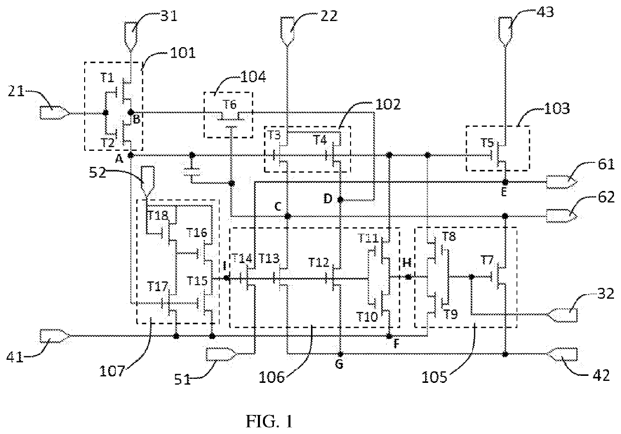
[0040]The display driving circuit provided by an embodiment of the present application can simultaneously output a positive pulse signal and a negative pulse signal, and the display driving circuit is composed of n-type transistors, and therefore can be completed by a same process in the process of manufacturing the display driving circuit. Compared with t...


PUM


Abstract

The present invention provides a method of driving a display panel and a driving device. The present invention determines sub-pixels shared by sub-pixel rendering technology through comparing differences of the color components, and the sub-pixels shared by the display image are not fixed. Since the sub-pixels with the smallest absolute value of the color component difference are selected for sharing, a contrast of an edge region of an image is improved, and distortion of an edge region of an image is reduced.

Description

BACKGROUND OF INVENTIONField of Invention[0001]The present application relates to the field of display technologies, and in particular, to a display driving circuit.Description of Prior Art[0002]In the field of display panels, at present, mainstream displays are divided into two types, namely liquid crystal displays and organic electroluminescent diode displays. Although imaging principles of a liquid crystal display and an organic electroluminescent diode display are different, both of them include pixel units arranged in an array. In order to realize a display function of a display, it is necessary to provide a scanning-signal to the pixel units row by row to drive the pixel units to work. The currently developed gate driver on array (GOA) technology, that is, the array substrate row driving technology, directly scans a driving circuit on an array substrate, thereby saving a space for separately setting the scanning driving circuit through an integrated chip, which is advantageous...

Claims


Application Information

Patent Timeline
IPC IPC(8): G09G3/20
CPCG09G3/20G09G2310/0267G09G2300/08G09G2310/08G09G2310/0264G09G2310/0286
Inventor ZHANG, LIUQIHAN, BAIXIANG
Owner SHENZHEN CHINA STAR OPTOELECTRONICS SEMICON DISPLAY TECH CO LTD
Why Eureka
Try Eureka