Image-forming apparatus and optical scanner

a technology of optical scanners and forming apparatuses, applied in the direction of electrical apparatus, instruments, printing, etc., can solve the problems of affecting the accuracy of color correction, so as to eliminate color misregistration and magnification deviations

Active Publication Date: 2005-02-17
RICOH KK
View PDF11 Cites 11 Cited by
  • Summary
  • Abstract
  • Description
  • Claims
  • Application Information

AI Technical Summary

Benefits of technology

[0048] According to the present invention, in each imaging optical system mounted in an image-forming apparatus, image writing magnification may be measured for each of divided regions in the main scanning direction and the image writing magnification may be corrected region by region. Accordingly, it is possible to eliminate the color misregistration and magnification deviations of an image in the main scanning direction. Further, according to the present invention, it is possible to realize an optical system in which distortion in the main scanning direction after fθ correction is controlled and that has an optimum characteristic adapted to each optical unit.

Problems solved by technology

In the case of forming an image by superposing several colors and in an optical system with emphasis on accuracy, such error components cause misregistration between color images, thus degrading image quality.
As a result, an increased number of pulses cannot be accommodated in such areas, thus preventing accurate correction from being performed.

Method used


Image

  • Image-forming apparatus and optical scanner
  • Image-forming apparatus and optical scanner
  • Image-forming apparatus and optical scanner

Examples


first embodiment

[0092] [First Embodiment]

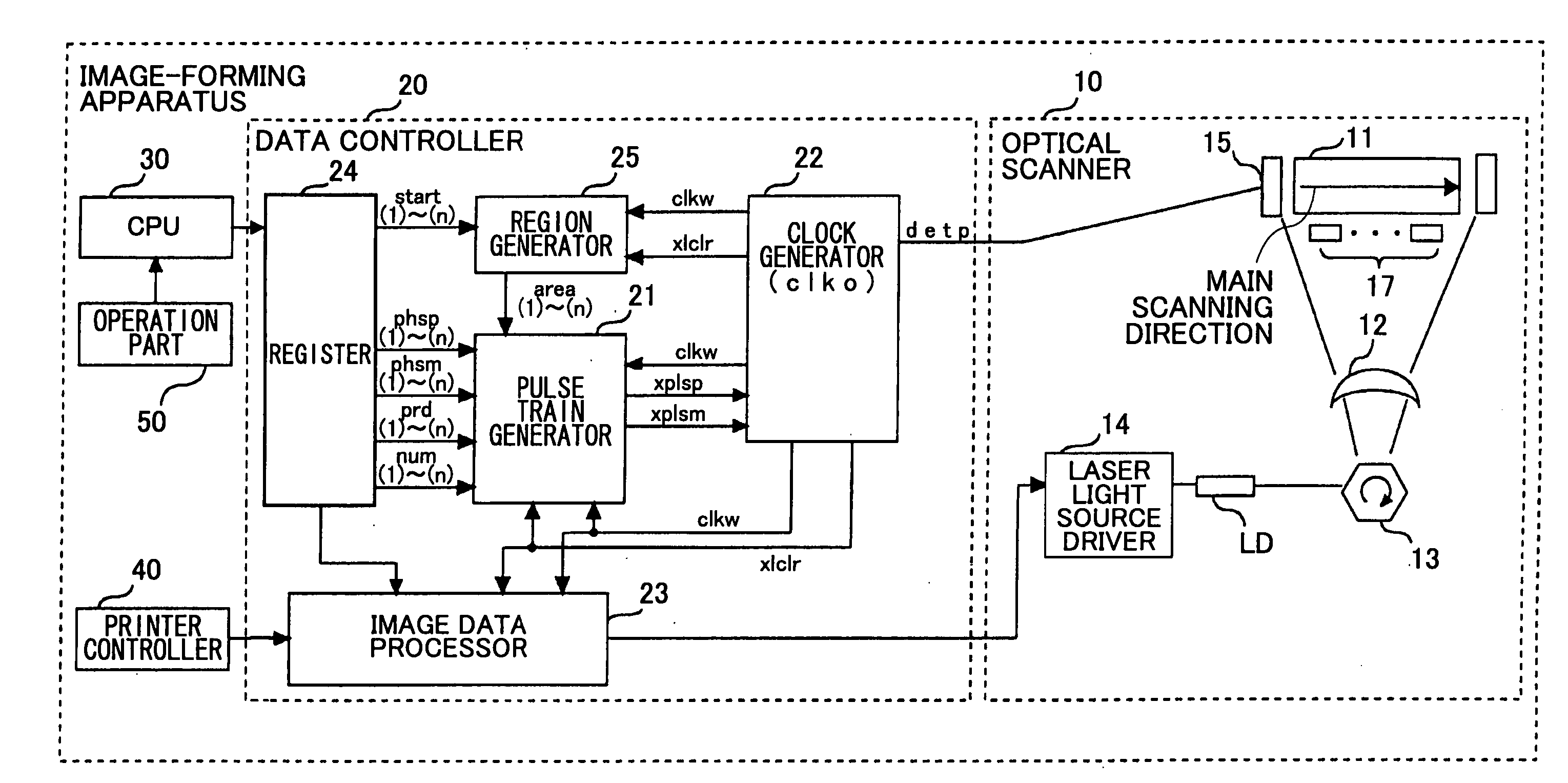
[0093]FIG. 8 is a block diagram showing an image-forming apparatus according to a first embodiment of the present invention. The image-forming apparatus may be, for instance, a printer, a copier, or a facsimile machine.

[0094] Referring to FIG. 8, the image-forming apparatus includes an optical scanner 10, a data controller 20, a central processing unit (CPU) 30, a printer controller 40, and an operation part 50 as an input part. The actual configuration of the image-forming apparatus is shown simplified in FIG. 8. The image-forming apparatus may have components other than those shown in FIG. 8.

[0095] The optical scanner 10, which forms an image using a laser beam, includes a photosensitive body 11 as a medium to be scanned, an fθ lens 12, a polygon mirror 13 as a rotary deflector, a laser light source driver 14, a synchronization detection part 15 as a synchronization detector, multiple position detection sensors 17, and a laser light source LD.

[0096] The...

second embodiment

[0226] [Second Embodiment]

[0227] Next, a description is given, with reference to FIG. 23, of the configuration and the operation of an image-forming apparatus according to the second embodiment of the present invention. FIG. 23 is a block diagram showing the image-forming apparatus according to this embodiment. The image-forming apparatus of the second embodiment may be equal in configuration and operation to the image-forming apparatus of the first embodiment unless otherwise specified. In the second embodiment, the same elements as those of the first embodiment are referred to by the same numerals.

[0228] Referring to FIG. 23, the image-forming apparatus includes the optical scanner 10, the data controller 20, the CPU 30, the printer controller 40, and the operation part 50 as an input part. The actual configuration of the image-forming apparatus is shown simplified in FIG. 23. The image-forming apparatus may have components other than those shown in FIG. 23.

[0229] The optical sc...

third embodiment

[0234] [Third Embodiment]

[0235] Next, a description is given, with reference to FIG. 24, of the configuration of an image-forming apparatus according to a third embodiment of the present invention. FIG. 24 is a block diagram showing the image-forming apparatus according to the third embodiment. In the third embodiment, the same elements as those of the first and second embodiments are referred to by the same numerals.

[0236] The image-forming apparatus may be, for instance, a printer, a copier, or a facsimile machine.

[0237] Referring to FIG. 24, the image-forming apparatus includes the optical scanner 10, the data controller 20, the CPU 30, the printer controller 40, the operation part 50 as an input part, and a reader unit 100. The actual configuration of the image-forming apparatus is shown simplified in FIG. 24. The image-forming apparatus may have components other than those shown in FIG. 24.

[0238] The optical scanner 10, which forms an image using a laser beam, includes the p...


PUM


Abstract

An image-forming apparatus is disclosed that includes at least one imaging optical system forming an electrostatic latent image on the scanning surface of a medium moving in a sub scanning direction by scanning the scanning surface in a main scanning direction by periodically deflecting a laser beam with a rotary deflector, a pixel clock generation part generating a pixel clock signal for controlling the emission timing of the laser beam and changing the phase of the pixel clock signal, a region setting part setting the length of each of multiple regions based on image writing magnifications in a line in the main scanning direction, the regions being formed by dividing part of the scanning surface corresponding to the line in the main scanning direction, and a phase control part controlling the changing of the phase of the pixel clock signal region by region based on the image writing magnifications.

Description

BACKGROUND OF THE INVENTION [0001] 1. Field of the Invention [0002] The present invention relates generally to image-forming apparatuses and optical scanners, and more particularly to an image-forming apparatus and an optical scanner that employ an LD (laser diode) optical system. [0003] 2. Description of the Related Art [0004] Some conventional image-forming apparatuses employ a laser beam to form an image. According to this laser-beam method, the image-forming apparatuses form an image by an optical scanner emitting a laser beam on the scanning surface (or the surface to be scanned) of a photosensitive body (a medium to be scanned). [0005] A description is given below, with reference to FIG. 1, of the operation of forming an image on a photosensitive body by an optical scanner according to the conventional laser-beam method. FIG. 1 is a diagram showing an image-forming operation by a conventional image-forming apparatus employing the laser-beam method. [0006] First, a charging uni...

Claims


Application Information

Patent Timeline
Patent Type & Authority Applications(United States)
IPC IPC(8): B41J2/44H04N1/036H04N1/053H04N1/113H04N1/12H04N1/23H04N1/29
CPCH04N1/053H04N1/1135H04N1/12H04N2201/0471H04N2201/04713H04N2201/04781H04N2201/04732H04N2201/04744H04N2201/04722H04N2201/04734H04N2201/04749H04N2201/04793
Inventor YOSHIDA, YOSHIKI
Owner RICOH KK
Why Eureka
Try Eureka