Electro-optical crystal light shutter preventing motion picture blurring in a liquid crystal display

a liquid crystal display and electrooptical technology, applied in non-linear optics, instruments, optics, etc., can solve the problems of edge blurring, higher power consumption in switching between the on/off state of the backlight lamp, and hold-type displays do not produce as good display performance, etc., to reduce the display time of an image, simplify circuit control, and reduce power consumption

Inactive Publication Date: 2005-02-17
HANNSTAR DISPLAY CORPORATION
View PDF10 Cites 15 Cited by
  • Summary
  • Abstract
  • Description
  • Claims
  • Application Information

AI Technical Summary

Benefits of technology

[0009] An object of the present invention is to provide a liquid crystal display (“LCD”) including an electro-optical light shutter (“EOLS”) to reduce a display time of an image during a frame time.
[0010] Another object of the present invention is to provide an LCD including an EOLS that has an emulated effect of a scanning backlight LCD to solve the edge blurring problems in displaying an image of a motion picture with simplified circuit control and less power consumption.
[0011] Still another object of the present invention is to provide an LCD including an EOLS that has an emulated effect of a scanning backlight LCD to solve the edge blurring problems in displaying an image of a motion picture without incurring the issue of light scattering on adjacent regions.
[0012] Further still another object of the present invention is to provide an LCD including an EOLS that has an emulated effect of a blinking backlight LCD to solve the edge blurring problems in displaying an image of a motion picture.

Problems solved by technology

The longer display time may result in problems of edge blurring in particular in displaying an image of a motion picture.
As a result, hold-type displays do not produce as good display performance as impulse-type displays.
Although the backlight scanning approach is able to solve the problems of edge blurring, a new issue of higher power consumption may arise in switching between the on / off states of the backlight lamps.
Another issue may also arise in the response speed of the backlight lamps.
However, backlight lamps with a faster response time are not reliable enough to meet commercial needs.
Still another issue may also arise in the sharpness of an image in display in that light emitted from an on-state lamp may scatter onto the regions to be illuminated by adjacent lamps which are currently turned off.
Besides, the blinking backlight approach also controls the on / off states of backlight lamps to reduce the display time of an image, and may thus have relatively high power consumption.
Although the scanning backlight approach and the blinking backlight approach may overcome the problems of edge blurring, both approaches require backlight lamps with a fast response time.
As mentioned above, such backlight lamps are not reliable enough.
Besides, both approaches have complex circuit control systems and relatively high power consumption due to switching between the on / off states of backlight lamps.

Method used


Image

  • Electro-optical crystal light shutter preventing motion picture blurring in a liquid crystal display
  • Electro-optical crystal light shutter preventing motion picture blurring in a liquid crystal display
  • Electro-optical crystal light shutter preventing motion picture blurring in a liquid crystal display

Examples


Embodiment Construction

[0028] Reference will now be made in detail to the present embodiment of the invention, an example of which is illustrated in the accompanying drawings. Wherever possible, the same reference numbers will be used throughout the drawings to refer to the same or like parts.

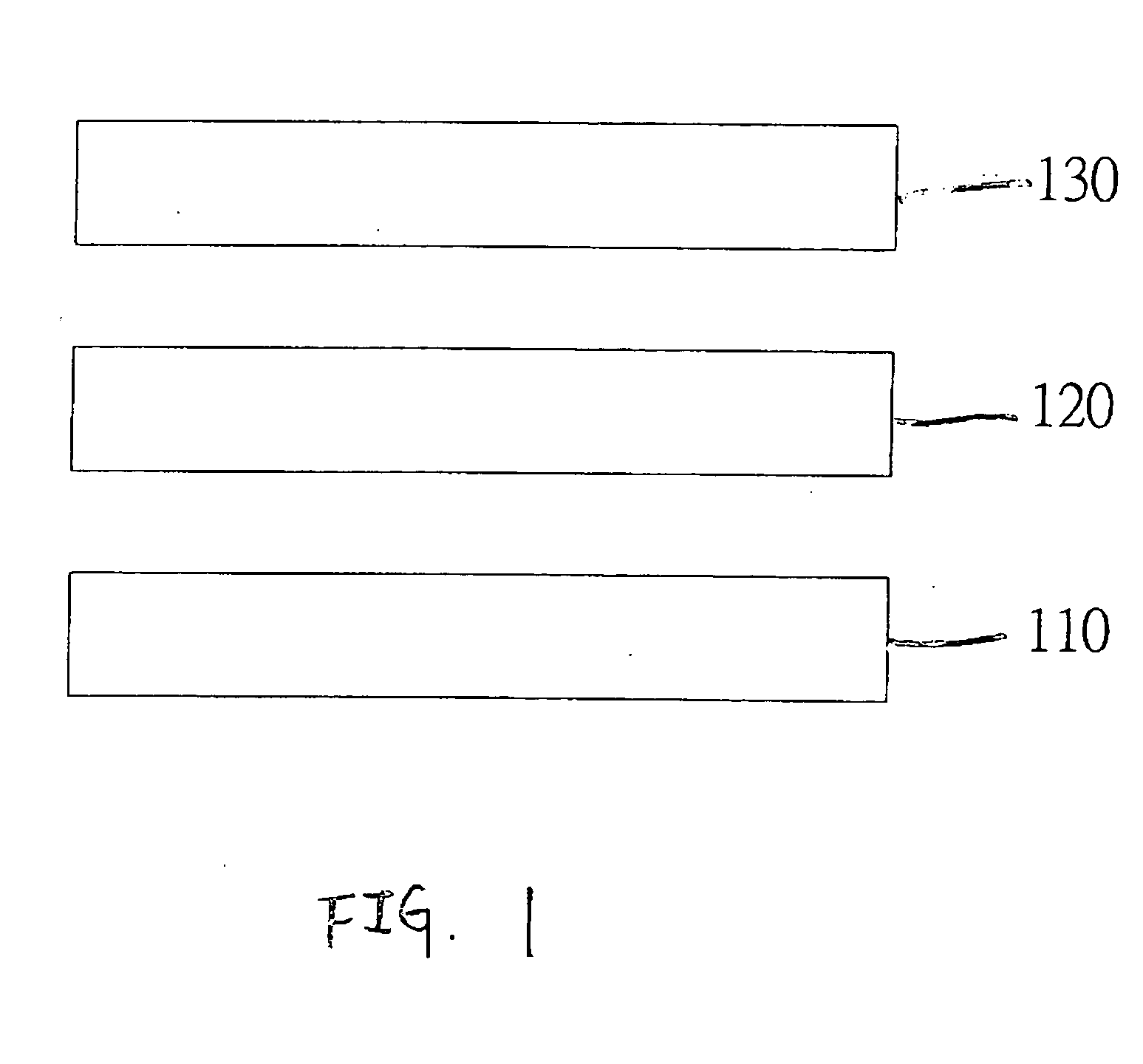
[0029]FIG. 1 is a schematic cross-sectional view of a liquid crystal display (LCD) including an electro-optical light shutter (EOLS) in accordance with one embodiment of the present invention. The LCD (not numbered) includes a backlight source 110, an electro-optical light shutter (EOLS) 120 and an LCD panel 130. Light emitted from backlight source 110 passes through EOLS 120 to LCD panel 130 to illuminate an image displayed on LCD panel 130. EOLS 120 turns on to become on-state or turns off to become off-state to control whether the light reaches LCD panel 130. The duration of the on-state or off-state controls a display time of an image during a frame time. EOLS 120 may include a solid-state crystal or a liquid cr...


PUM

PropertyMeasurementUnit
response timeaaaaaaaaaa
timeaaaaaaaaaa

Abstract

A liquid crystal display (LCD) that comprises a backlight source, an electro-optical light shutter (EOLS) including a plurality of regions arranged in a pattern, and during a frame time controlling light from the backlight source to pass the regions in a display time that allows the LCD to display an image, and an LCD panel disposed to sandwich the EOLS with the backlight source receiving the light passing through the EOLS to display the image.

Description

FIELD OF THE INVENTION [0001] This invention relates in general to a liquid crystal display (“LCD”) and, more particularly, to an LCD including an electro-optical light shutter. BACKGROUND OF THE INVENTION [0002] Display devices in the art may generally be divided into impulse-type displays and hold-type displays according to their principles of display. An impulse-type display, for example, a cathode ray tube (“CRT”) display, provides luminance signals in the form of a serial of impulses in displaying an image. The image exists for a relatively short time during a frame time. [0003] On the other hand, a hold-type display, for example, a liquid crystal display (“LCD”), provides luminance signals in the form of a serial of square waves in displaying an image. The image displayed by a hold-type display exists longer than that displayed by an impulse-type display during a frame time. The longer display time may result in problems of edge blurring in particular in displaying an image of...

Claims


Application Information

Patent Timeline
Patent Type & Authority Applications(United States)
IPC IPC(8): G02F1/1347
CPCG02F1/13471
Inventor LAI, CHI-KUANG
Owner HANNSTAR DISPLAY CORPORATION
Why Eureka
Try Eureka