Vacuum-cavity MEMS resonator

a mems resonator and vacuum cavity technology, applied in the field of microelectromechanical systems, can solve the problems of relatively complicated mems packaging and dedicated alignment/bonding technology, and the process is difficult to control

Inactive Publication Date: 2005-02-17
INTEL CORP
View PDF3 Cites 101 Cited by
  • Summary
  • Abstract
  • Description
  • Claims
  • Application Information

AI Technical Summary

Problems solved by technology

A challenge in fabricating MEMS resonators is the vacuum packaging step.
However, these techniques require dedicated alignment / bonding technologies that are relatively complicated to apply to MEMS packaging.
While conceptually simple, such a process has proven very difficult to control and has yet to lead to a manufacturable MEMS resonator vacuum packaging process.

Method used


Image

  • Vacuum-cavity MEMS resonator
  • Vacuum-cavity MEMS resonator
  • Vacuum-cavity MEMS resonator

Examples


Embodiment Construction

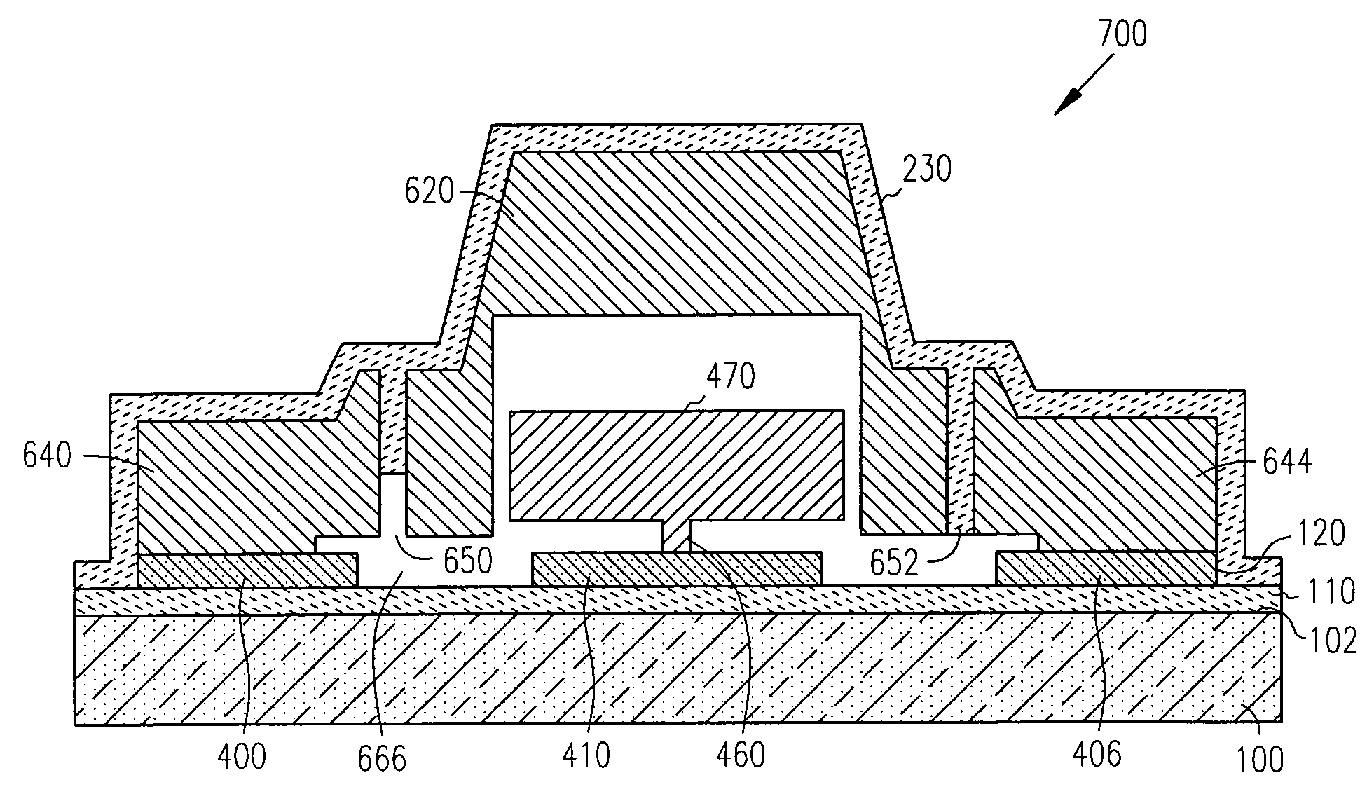
[0018] The present invention provides vacuum cavities for MEMS resonators by a film deposition and release process that does not add a significant number of additional steps to the MEMS resonator fabrication process.

[0019] In the following detailed description of the embodiments of the invention, reference is made to the accompanying drawings that form a part hereof, and in which is shown by way of illustration specific embodiments in which the invention may be practiced. These embodiments are described in sufficient detail to enable those skilled in the art to practice the invention, and it is to be understood that other embodiments may be utilized and that changes may be made without departing from the scope of the present invention. The following detailed description is, therefore, not to be taken in a limiting sense, and the scope of the present invention is defined only by the appended claims.

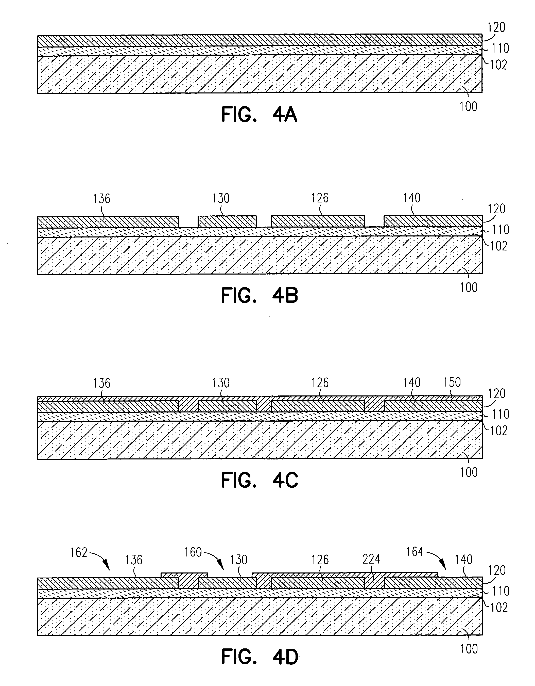
[0020] Cantilever-Beam MEMS Resonator (FIGS. 4A-4K)

[0021] In FIG. 4A, the method be...


PUM


Abstract

A microelectromechanical (MEMS) resonator with a vacuum-cavity is fabricated using polysilicon-enabled release methods. A vacuum-cavity surrounding the MEMS beam is formed by removing release material that surrounds the beam and sealing the resulting cavity under vacuum by depositing a layer of nitride over the structure. The vacuum-cavity MEMS resonators have cantilever beams, bridge beams or breathing-bar beams.

Description

[0001] This application is a divisional of U.S. patent application Ser. No. 09 / 949,368 filed on Sep. 7, 2001, and incorporated herein by reference.FIELD OF THE INVENTION [0002] The present invention relates to microelectromechanical systems (MEMS), and in particular to vacuum cavity packaging of MEMS resonators. BACKGROUND OF THE INVENTION [0003] A resonator is an electronic device used for setting up and maintaining an oscillating electrical signal of a given frequency. Conventional resonators typically include electronic circuitry in combination with a mechanical oscillator element (e.g., a quartz crystal, a ceramic element or a resonance circuit). Resonators are used in many electronic devices, such wireless radio frequency (RF) equipment, for generating outgoing signals of a particular frequency, and filtering incoming signals. [0004] In most electronic devices that require signal generation and filtering, conventional resonators are used. Such resonators have a high Q-factor (i...

Claims


Application Information

Patent Timeline
Patent Type & Authority Applications(United States)
IPC IPC(8): B81B7/00H03H3/007H03H9/10H03H9/24
CPCB81B7/0077H03H3/0072H03H9/1057H03H9/2405H03H2009/02511H03H9/2457H03H9/2463H03H2009/02503H03H9/2431
Inventor MA, QINGCHENG, PENGRAO, VALLURI
Owner INTEL CORP
Why Eureka
Try Eureka