
Apparatus and method for enabling different reduced slot cycle modes in a wireless network

a wireless network and reduced slot technology, applied in the field of wireless networks, can solve the problems of inability to operate with full cycle slotted mode periods of 1.28 seconds, inability to properly operate real-time interactions, and limited operation period of internal batteries

Inactive Publication Date: 2005-02-17
SAMSUNG ELECTRONICS CO LTD
View PDF3 Cites 49 Cited by
  • Summary
  • Abstract
  • Description
  • Claims
  • Application Information

AI Technical Summary

Benefits of technology

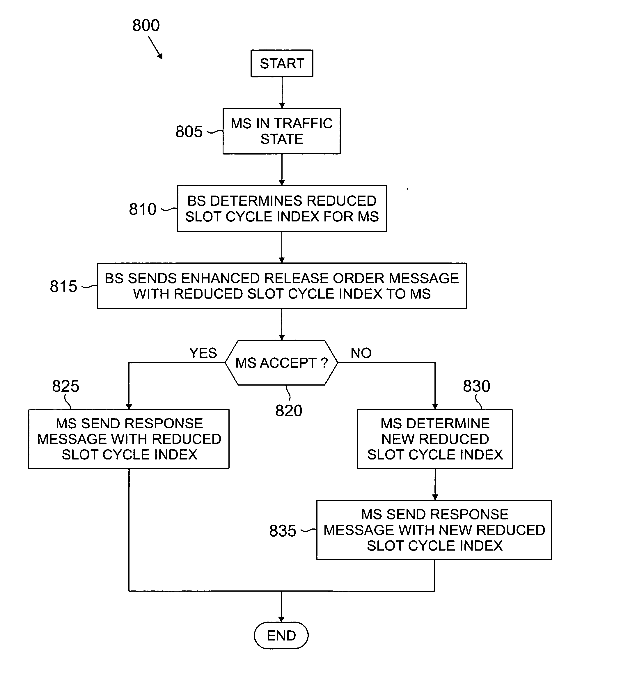
According to one embodiment of the present invention, the reduced slot cycle controller is further capable of causing the base station to transmit an additional enhanced release order message to a second one of the plurality of mobile stations, wherein the additional enhanced release order message comprises a first data field containing a second reduced slot cycle index value to be used by the second mobile station.

Problems solved by technology

When the external power source is not connected, an internal battery provides a limited period of operation.
Many of these new features cannot operate with full cycle slotted mode periods of 1.28 seconds or greater.
However, a gaming application that requires fast, real-time interactions cannot properly operate in a slotted mode that has a minimum period of 1.28 seconds.
Another new application that is adversely affected by full cycle slotted mode operation is Push-to-Talk service, such as the Direct ConnectSM service available from Nextel.
However, a Push-to-Talk application cannot properly operate with a slotted mode that has a minimum period of 1.28 seconds.
Unfortunately, the widespread use of reduced slot cycle mode by a large number of mobile stations creates considerable scheduling problems in the base station.
However, when slot cycles are only 80 milliseconds long, the base station is less able to schedule transmissions in an optimal manner.
Continually operating the second group of mobile stations in the reduced slotted mode unnecessarily drains the batteries of the second group of mobile stations and reduces battery life.
However, operating the first group of mobile stations in a normal mode of operation (non-reduced slotted mode) has a negative impact on application performance.

Method used


Image

  • Apparatus and method for enabling different reduced slot cycle modes in a wireless network
  • Apparatus and method for enabling different reduced slot cycle modes in a wireless network
  • Apparatus and method for enabling different reduced slot cycle modes in a wireless network

Examples


Embodiment Construction

FIGS. 1 through 8, discussed below, and the various embodiments used to describe the principles of the present invention in this patent document are by way of illustration only and should not be construed in any way to limit the scope of the invention. Those skilled in the art will understand that the principles of the present invention may be implemented in any suitably arranged wireless network.

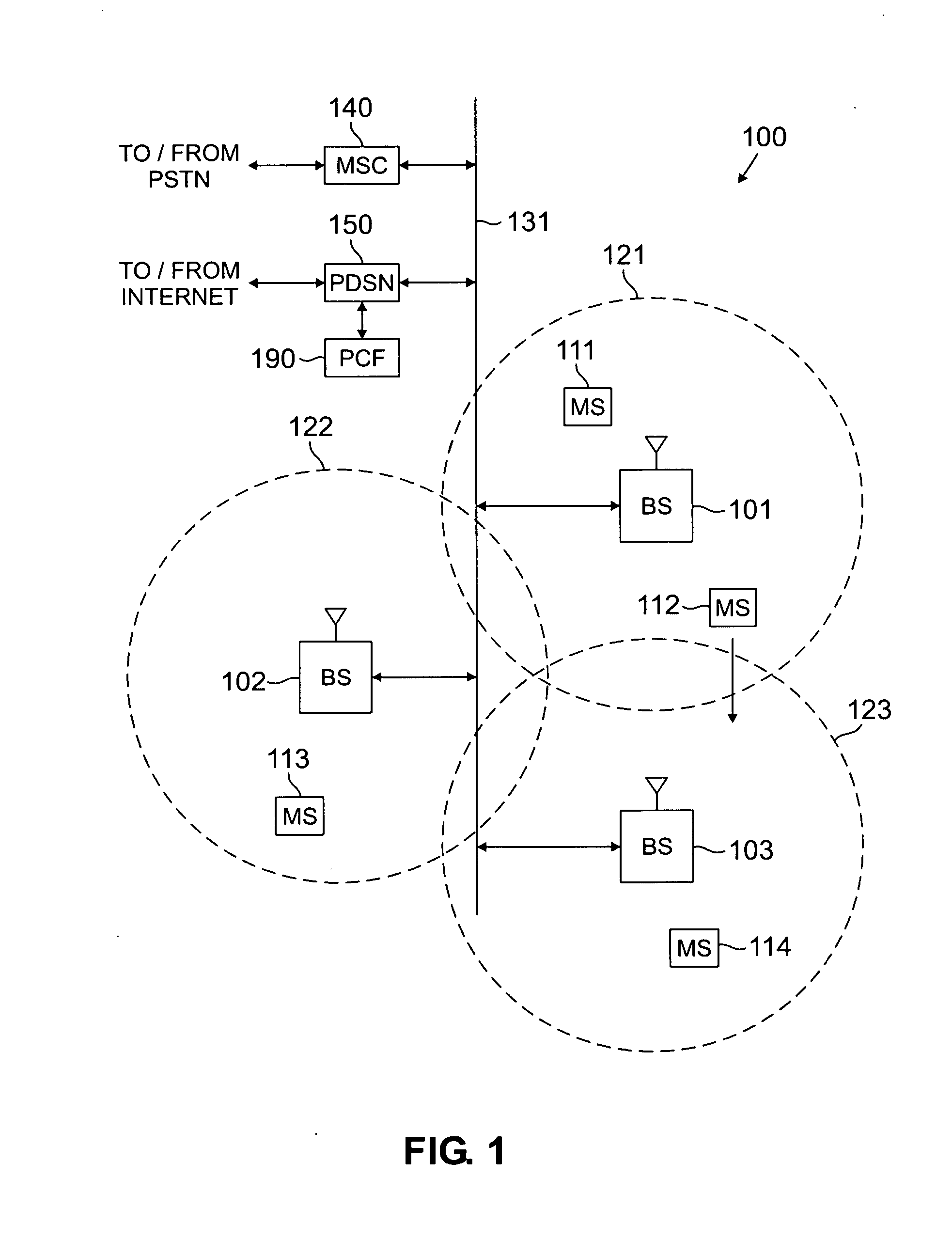
FIG. 1 illustrates exemplary wireless network 100 in which base stations control the use of the reduced slot cycle mode of operation by mobile stations according to the principles of the present invention. Wireless network 100 comprises a plurality of cell sites 121-123, each containing one of the base stations, BS 101, BS 102, or BS 103. Base stations 101-103 communicate with a plurality of mobile stations (MS) 111-114 over code division multiple access (CDMA) channels according to, for example, the IS-2000-C standard (i.e., Release C of cdma2000). In an advantageous embodiment of the pres...


PUM


Abstract

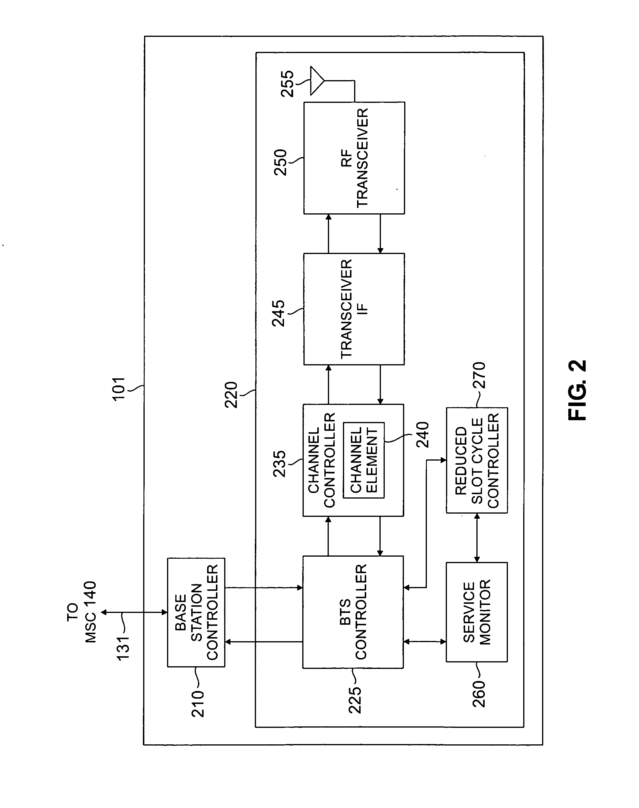
A wireless network base station in communication with a mobile station enables the use of the reduced slot cycle mode by the mobile station. The base station comprises a reduced slot cycle controller that causes the base station to transmit an enhanced release order message to the mobile station to transition the mobile station from a traffic state to an idle state. The enhanced release order message comprises a first data field containing a first reduced slot cycle index (SCI) value to be used by the mobile station.

Description

TECHNICAL FIELD OF THE INVENTION The present invention is generally related to wireless networks and, in particular, to a wireless network capable of enabling different reduced slot cycle modes. BACKGROUND OF THE INVENTION Wireless communication systems have become ubiquitous in society. Business and consumers use a wide variety of fixed and mobile wireless terminals, including cell phones, pagers, Personal Communication Services (PCS) systems, and fixed wireless access devices (e.g., vending machine with cell phone capability). Wireless service providers continually try to create new markets for wireless devices and expand existing markets by making wireless devices and services cheaper and more reliable. The prices of wireless devices have decreased to the point where nearly everyone can afford them. To continue to attract new customers, wireless service providers are implementing new services, especially digital data services that, for example, enable a user (or subscriber) to ...

Claims


Application Information

Patent Timeline
IPC IPC(8): H04W68/00H04W76/06
CPCH04W76/06H04W68/00H04W76/30
Inventor RAJKOTIA, PURVA R.KODALI, SANJAYKUMAR
Owner SAMSUNG ELECTRONICS CO LTD
Learn More