

Method for manufacturing light guide plate stamper
- Summary
- Abstract
- Description
- Claims
- Application Information
AI Technical Summary
Benefits of technology
Problems solved by technology
Method used
Image

Examples
Embodiment Construction
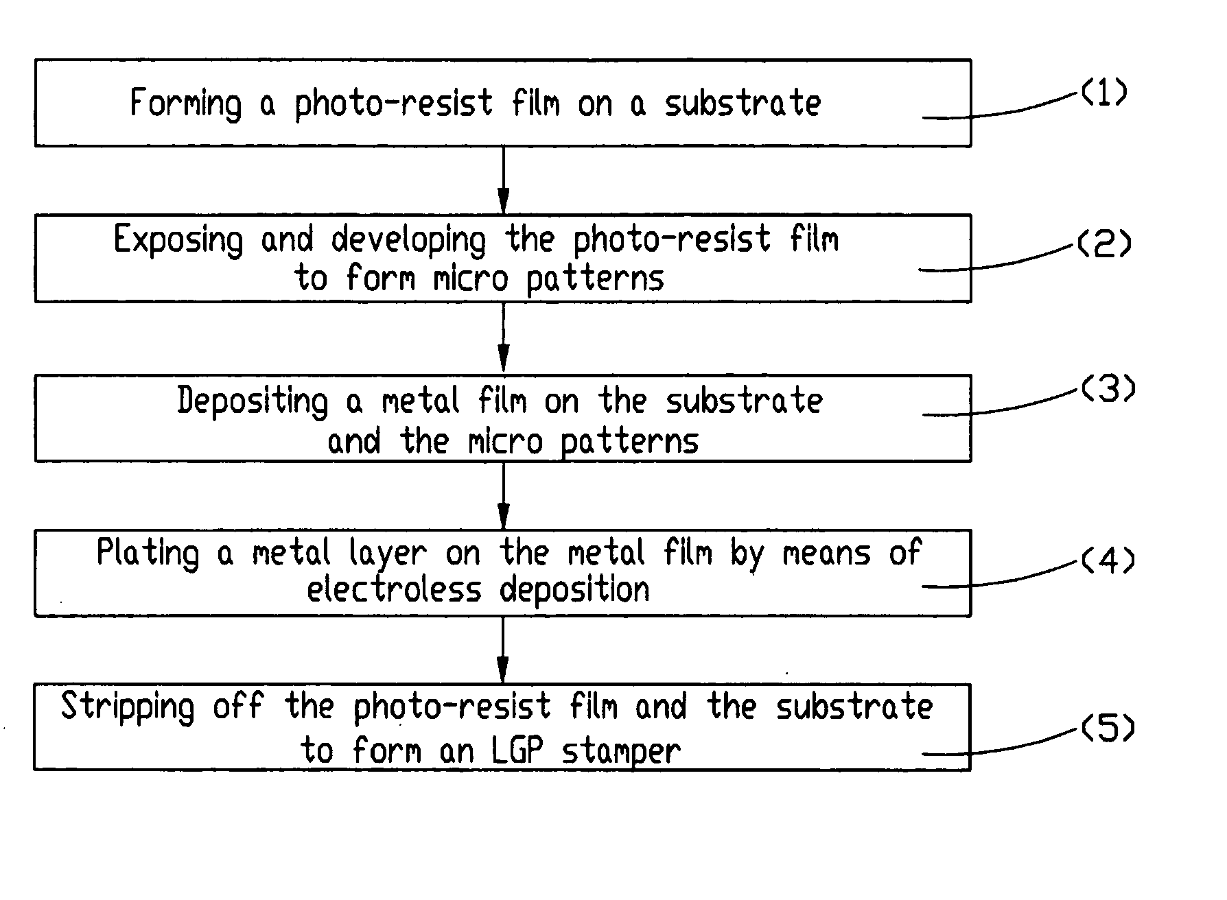
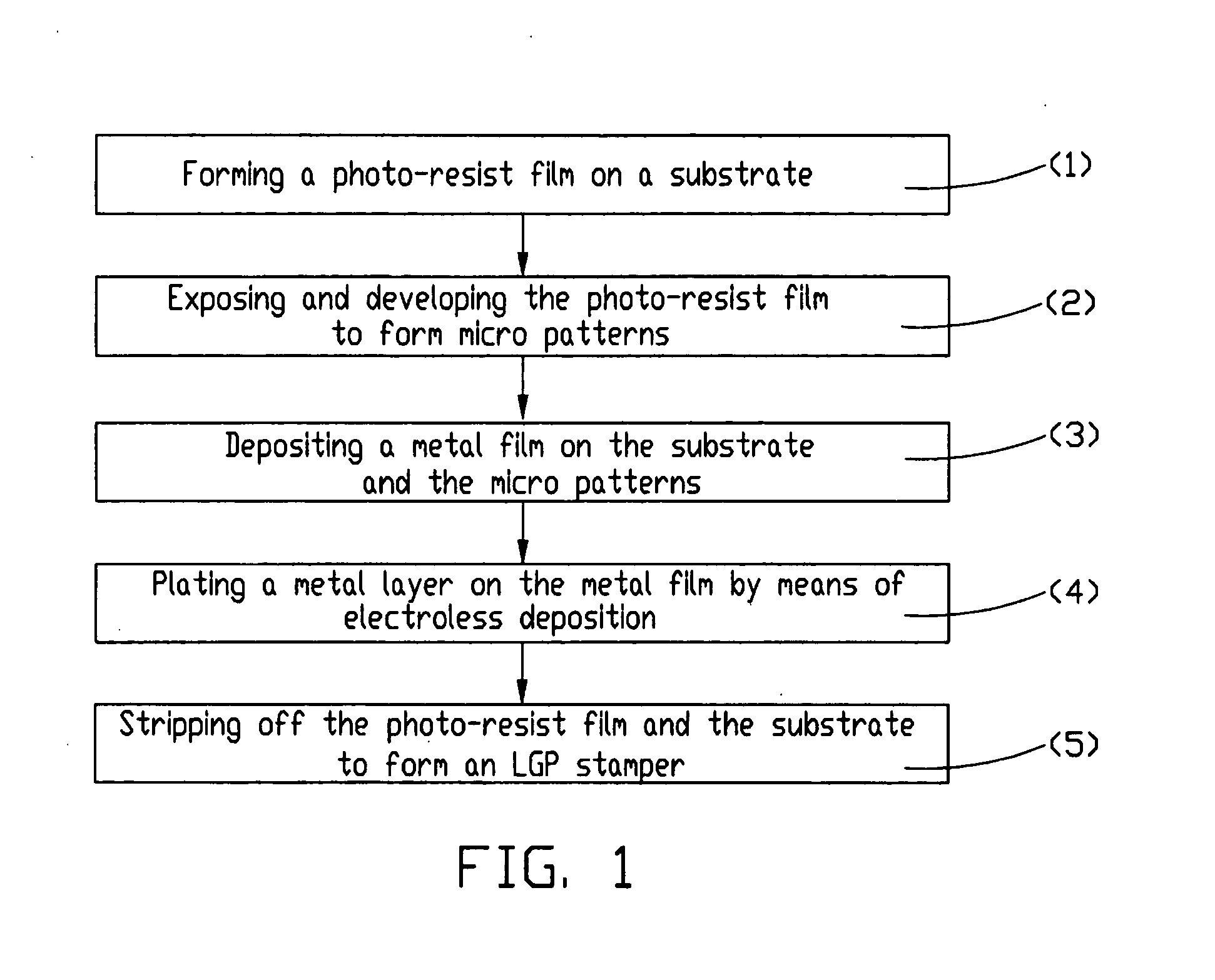
[0017] The preferred embodiment of the method for manufacturing an LGP stamper having highly precise micro patterns according to the present invention will be described with reference to the flowchart of FIG. 1.
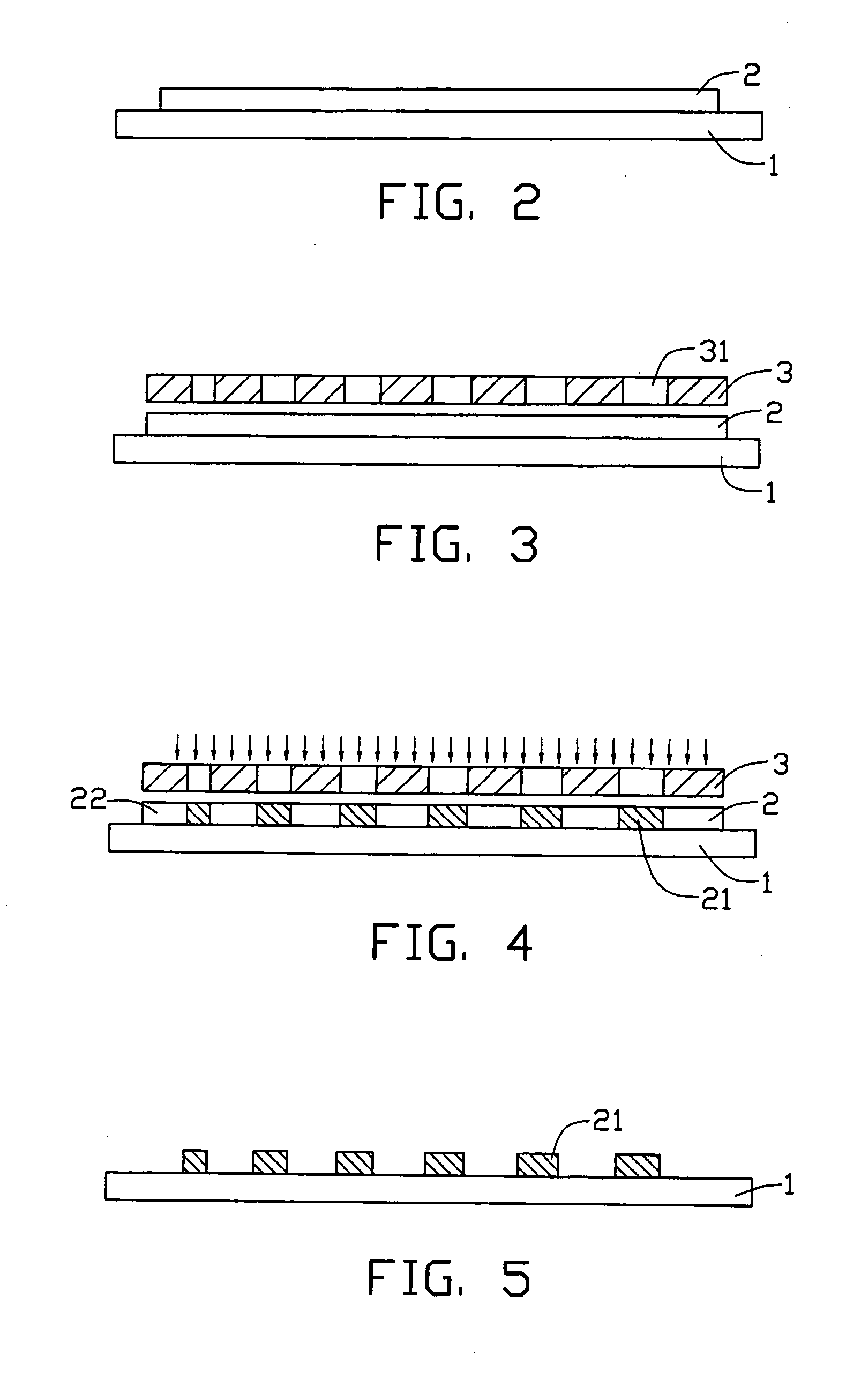
[0018] (1) Providing a glass substrate 1, and forming a photo-resist film 2 on the substrate 1 (see FIG. 2). First, the substrate 1 with a smooth surface and a thickness of 2 to 10 millimeters is provided. An adhesion promoting agent of the silane series is then applied on the substrate 1. Second, the substrate 1 is placed on a coating machine (not shown). The photo-resist film 2 is coated on the substrate 1 to a thickness of about 20 microns. Third, the photo-resist film 2 is baked at 140° C. for two hours.
[0019] The coating process may be a spin coating process, a roll coating process, or a like process. A liquid or film-like positive or negative photo-resist material can be used. The substrate 1 may alternatively be substituted with a silicon wafer.
[0020] (2) Exposing a...
PUM
 Abstract
Description
Claims
Application Information