Deformation medical device without material deformation

a medical device and material technology, applied in the field of medical devices, can solve the problems of existing stent designs that are incompatible with mri visualization, unable to meet the requirements of mri visualization, and the use of a material, such as ceramic, can present its own challenges

Inactive Publication Date: 2005-02-17
BOSTON SCI SCIMED INC
View PDF52 Cites 196 Cited by
  • Summary
  • Abstract
  • Description
  • Claims
  • Application Information

AI Technical Summary

Benefits of technology

[0009] One embodiment of the present invention thus provides a medical device, such as a stent, made of a relatively inflexible material yet which can still be moved from the crimped or radially contracted insertion position to the radially expanded deployed position. In one embodiment, portions of the stent are made out of relatively inflexible material and are connected together with a hinge connection. This allows the stent to incorporate materials having relatively low ultimate strain values, such as ceramics, without subjecting these materials to high strain or stress values. This also allows the stent to be assembled on top of a deployment balloon, completely avoiding the crimping process.
[0011] In yet another embodiment, the stent is provided with sliding elements that allow the stent to expand and contract without stressing the stent material. Thus, the stent can be made of a sheet of rolled material that overlaps itself, and the sliding elements interact so the stent can be expanded to a desired diameter.

Problems solved by technology

Another problem associated with conventional stents involves magnetic resonance imaging (MRI) visualization.
However, existing stent designs are incompatible with MRI visualization due to the permanent magnetic disturbance as a result of the magnetic susceptibility of the metals being used as well as the dynamic disturbance of the magnetic field due to Faraday's law as a result of the strong radio frequency (RF) fields and switched gradient magnetic fields in MRI systems in combination with the metallic cage construction of stents.
However, using a material, such as ceramic, can present its own challenges.
Ceramics are more biocompatible, stronger and more durable than polymers, but are less flexible.
Thus, ceramics have a disadvantage in that they perform very poorly in tensile situations.
Also, due to their elongation properties, which are virtually non-existent, it is nearly impossible to bend a ceramic.
These types of integrated material stents also suffer from another disadvantage.
To remove metal sections out of a finished stent and then to glue ceramic pieces, similar in geometry, into the place where the metal is removed is quite a cumbersome task.
It is very difficult to position an extremely small ceramic piece within the complex metal structure of a stent during a bonding operation.
Similarly, due to the relatively high number of processing steps needed to produce stents (such as laser cutting, polishing, etc.) tolerance buildup yields variation in the cross-section size of the struts of the stent, which makes it virtually impossible to create exactly matching ceramic pieces.
Therefore, using this technique to create a more MRI compatible stent has economic drawbacks, particularly if the process must be repeated up to 10-30 times for every stent.

Method used


Image

  • Deformation medical device without material deformation
  • Deformation medical device without material deformation
  • Deformation medical device without material deformation

Examples


Embodiment Construction

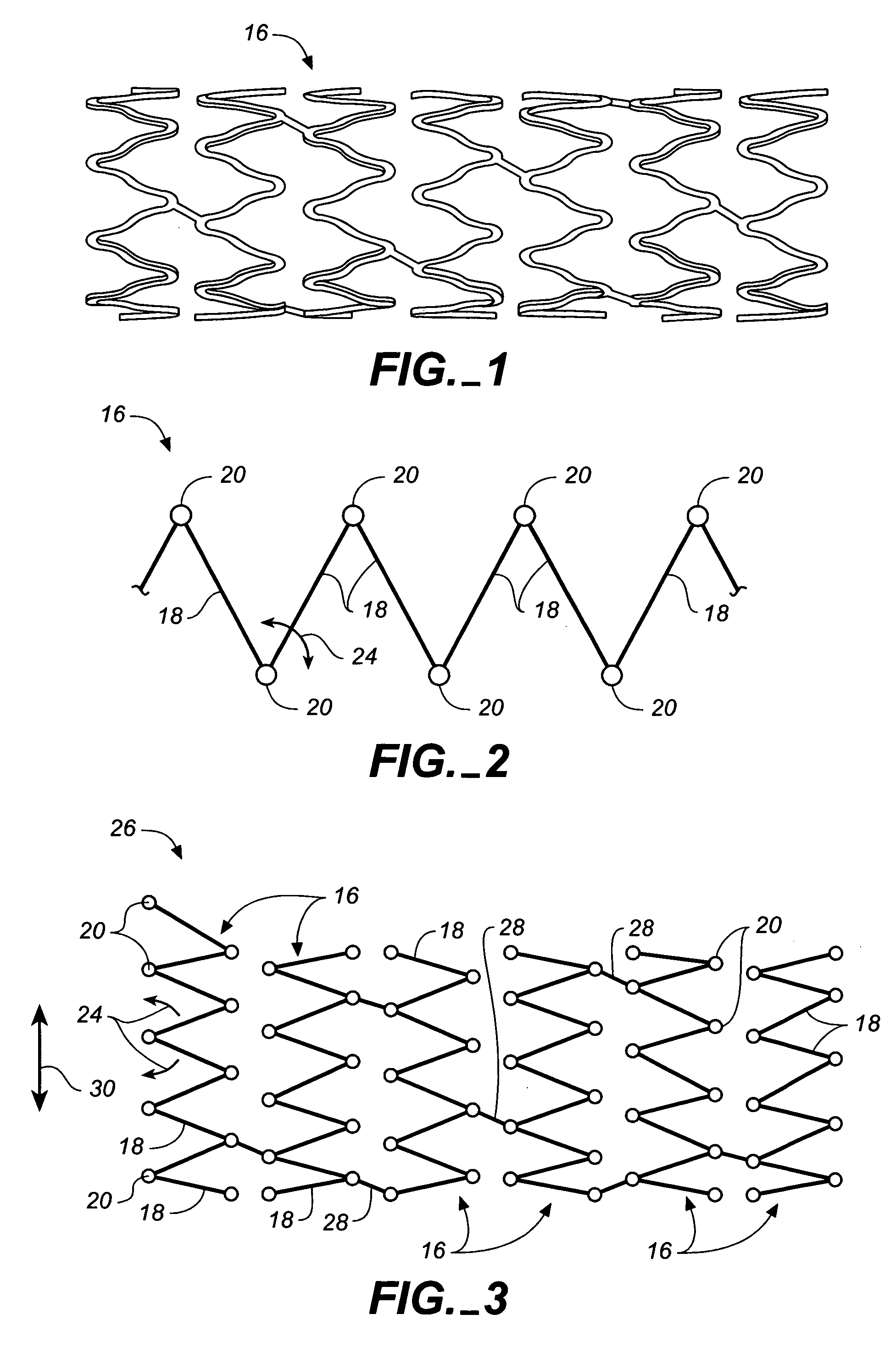
[0023]FIG. 1 is a schematic drawing of a segmented stent 10 in accordance with a conventional design. Stent 10 is illustrated as a closed cell design in which a plurality of closed cell stent segments or struts 12 are interconnected by connectors 14. Stent 10, in the past, has been formed as a self-expandable type of stent made of self-expanding material, such as Nitinol. Such stents are cut or etched from tubular stock or rolled or cut or etched from flat sheets of Nitinol or other shape memory metals, which do not themselves exhibit permanent deformation. In general, the self-expanding stent design tends to return to its unconstrained or expanded conformation.

[0024] Alternatively, stent 10 has been formed as an expandable stent, which is expandable under an externally applied pressure that is applied to the stent in a radially outward direction. Such stents are typically crimped around an expansion balloon and inserted to a desired position in the vasculature. The balloon is then...


PUM


Abstract

One embodiment of the present invention provides a stent made of a relatively inflexible material yet which can still be moved from the crimped or radially contracted insertion position to the radially expanded deployed position. In one embodiment, portions of the stent are made out of relatively inflexible material and are connected together with a hinge connection.

Description

BACKGROUND OF THE INVENTION [0001] The present invention deals with medical devices. More specifically, the present invention deals with medical devices, such as stents, that can be deployed without undergoing material deformation. [0002] Stents are well known for use in opening and reinforcing the interior wall of blood vessels and other body conduits. Stents are generally tubular, radially expandable and may be of a self-expanding type or can be expandable with an outwardly directed pressure applied to the stent, typically by expansion of an interiorly positioned balloon. Stents are conventionally made of various materials such as plastic or metal. [0003] Conventional stents suffer from a number of disadvantages. One of the problems associated with conventional stents is that current stent designs are limited in the amount of diameter change which can be obtained with the stent as it moves from an unexpanded, insertion position, to an expanded, deployed position. The relative chan...

Claims


Application Information

Patent Timeline
Patent Type & Authority Applications(United States)
IPC IPC(8): A61F2/92
CPCA61F2/91A61F2/915A61F2/92A61F2230/0054A61F2002/91558A61F2002/91591A61F2002/91533
Inventor NEUENDORF, RACHELWEBER, JAN
Owner BOSTON SCI SCIMED INC
Why Eureka
Try Eureka