Coordinates input device

a technology of input device and coordinates, which is applied in the direction of mechanical pattern conversion, instruments, computing, etc., can solve the problems of difficult to obtain a satisfactory thrust, touch panel depress cannot be sensed, and conventional touch panel does not provide the feeling of a click

Inactive Publication Date: 2005-02-17
FUJITSU COMPONENENT LTD
View PDF1 Cites 44 Cited by
  • Summary
  • Abstract
  • Description
  • Claims
  • Application Information

AI Technical Summary

Benefits of technology

[0009] It is an object of the present invention to provide a coordinates input device capable of producing a large magnitude of thrust on an operation unit.

Problems solved by technology

The conventional touch panel does not provide the feeling of a click, which may be provided in a key switch of the keyboard.
Thus, depressing on the touch panel cannot be sensed, which may induce an erroneous operation.
However, the touch panel device disclosed in Document 1 has the following problem.
Thus, it is very difficult to obtain a satisfactory thrust and produce a large magnitude of vibration on the touch panel.
Thus, it is very difficult to obtain a satisfactory thrust and produces a large magnitude of vibration on the touch panel.
Further, the two-dimensional vibration is produced in parallel with the touch panel, so that only a limited number of vibratory patterns can be obtained.

Method used


Image

  • Coordinates input device
  • Coordinates input device
  • Coordinates input device

Examples


first embodiment

[0036] (First Embodiment)

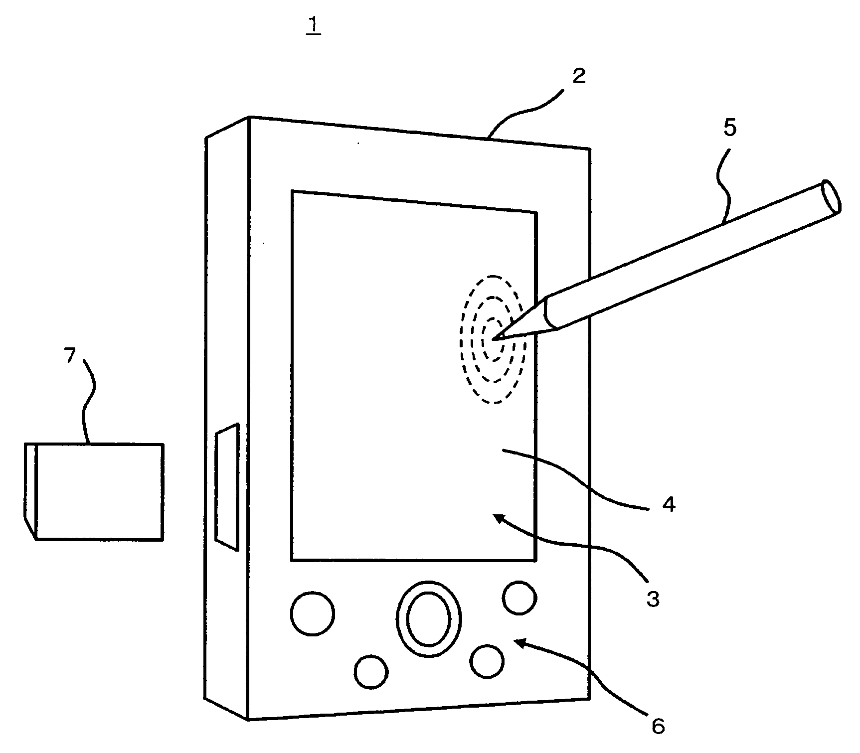
[0037]FIG. 1 is a perspective view of a portable electronic device 1 according to a first embodiment of the present invention, and FIG. 2 is a diagram of a structure of the portable electronic device 1 shown in FIG. 1. The device 1 has a main body case 2 having a window via which a display screen of a display unit 3 is exposed. A transparent touch panel 4 is provided on the display screen. The user may touch the touch panel 4 with an attached pen 5 or finger, so that an instruction to the portable electronic device 1 can be input thereto.

[0038] Operation keys 6 of depression type are provided on the front panel of the main body case 2 and a reused to input instructions to the portable electronic device 1. A memory card 7 can be loaded into the portable electronic device 1. One of the operation keys 6 may be a main power switch.

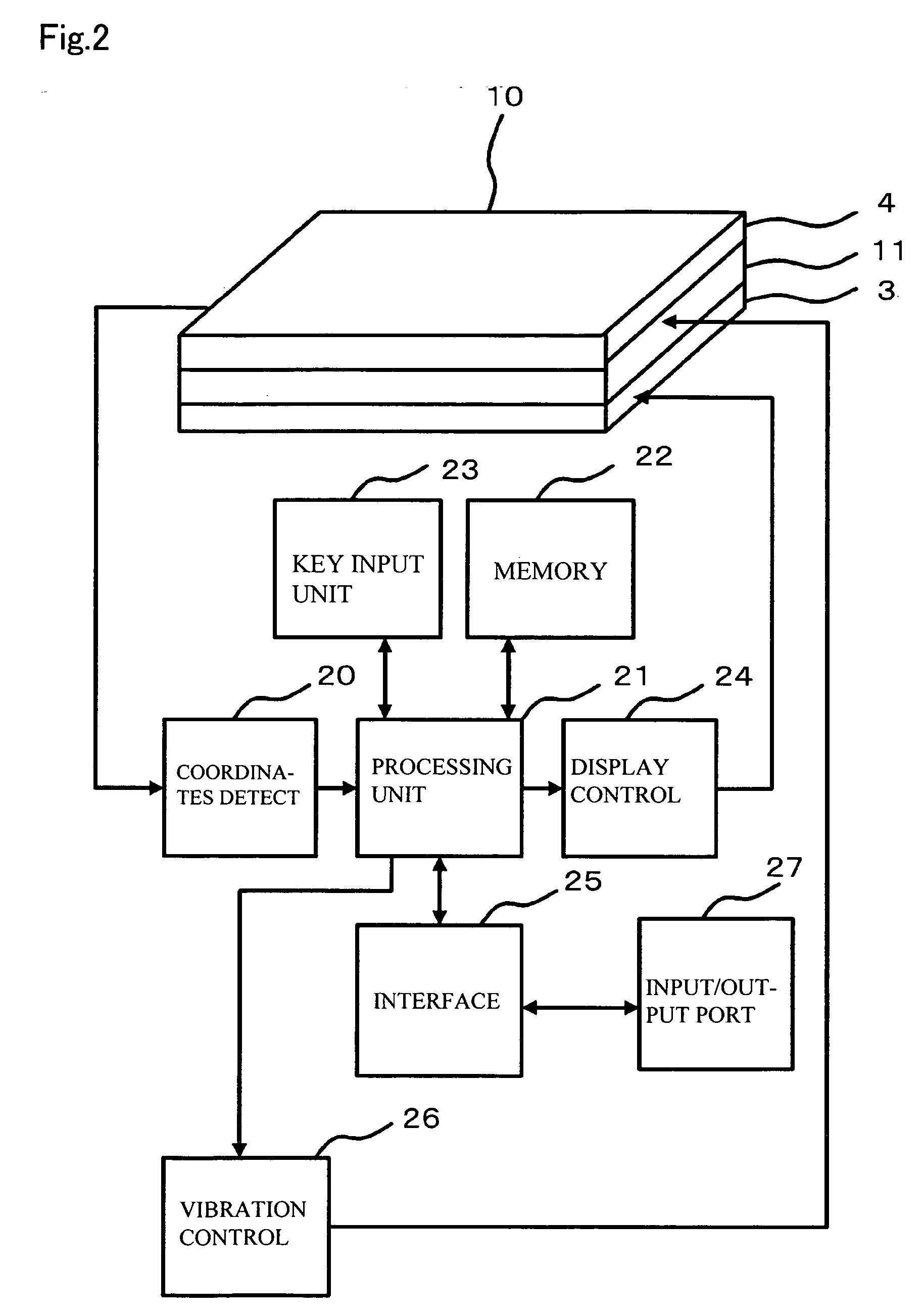
[0039] As shown in FIG. 2, the portable electronic device 1 has a panel unit 10, a coordinates detection unit 20, a processing unit...

second embodiment

[0057] (Second Embodiment)

[0058] A description will now be given of a coordinates input device equipped with another vibration generator according to a second embodiment of the present invention. FIG. 9 shows such a vibration generator, which corresponds to the vibration generator of the first embodiment shown in FIG. 5. In FIG. 9, the transparent resin films 14 are not illustrated for the sake of convenience. A vibration generator 41 employed in the second embodiment of the invention includes the coil 15, the first magnet 16, the second magnet 17, the yoke 18, and a spacer 42. In FIG. 9, parts that are the same as those shown in the previously described figures are given the same reference numerals.

[0059] The spacer 42 is provided in the gap G1 between the first magnet 16 and the second magnet 17. The spacer 42 improves the degree of precision in positioning the gap G1. Preferably, the spacer 42 is made of a nonmagnetic material.

[0060] According to the second embodiment, the spac...

third embodiment

[0061] (Third Embodiment)

[0062]FIG. 10 is an exploded perspective view of a panel unit employed in a coordinates input device according to a third embodiment of the present invention. FIG. 10 corresponds to FIG. 3 of the first embodiment. FIG. 11 schematically illustrates an arrangement of the vibration generator employed in the third embodiment, and shows a view of the touch panel 4 from the magnetic-field applying unit 14 shown in FIG. 10. In FIGS. 10 and 11, parts that are the same as those shown in the previously described figures are given the same reference numerals.

[0063] As shown in FIG. 10, a panel unit 110 includes the touch panel 4, a vibration generator 111, and the display unit 3. The vibration generator 111 has a first power feed unit 112, a second power feed unit 113, and the magnetic-field applying unit 14. The first power feed unit 112 and the second power feed unit 113 are arranged along two opposing sides of the touch panel 4. The power feed unit 112 has a coil 1...


PUM


Abstract

A coordinates input device includes an operation unit that receives an operation input, a vibration generator that applies a vibration to the operation unit, and a vibration control unit that controls the vibration generator to apply the vibration to the operation unit when the operation input is received by the operation unit. The vibration generator includes a power feed unit provided to the operation unit, and a magnetic-field applying unit having sub-units. Each of the sub-units has first and second magnets spaced apart from each other with a given gap. The magnetic flux produced by the first and second magnets crosses a current flowing in the power feed unit.

Description

BACKGROUND OF THE INVENTION [0001] 1. Field of the Invention [0002] The present invention relates to a coordinates input device. [0003] 2. Description of the Related Art [0004] A device equipped with a touch panel or touch pad uses a touch operation in which the touch panel is touched with a pen or finger. The conventional touch panel does not provide the feeling of a click, which may be provided in a key switch of the keyboard. Thus, depressing on the touch panel cannot be sensed, which may induce an erroneous operation. There is a proposal to use vibration to have the operator sense his / her operation on the touch panel or pad. [0005] Japanese Laid-Open Patent Application Publication No. 2002-149312 (Document 1) discloses a portable electronic device equipped with a vibratory actuator composed of a coil and a magnet. A drive signal generating circuit drives the vibratory actuator to produce vibration when an input operation on the touch panel or operation key is accepted. [0006] Ja...

Claims


Application Information

Patent Timeline
Patent Type & Authority Applications(United States)
IPC IPC(8): G06F3/041G06F3/01G06F13/00
CPCG06F3/016
Inventor HARADA, KEITAKURASHIMA, SHIGEMISHIMIZU, NOBUYOSHINAKAMURA, AKIONISHIYAMA, YURIKOAKIEDA, SHINICHIROARITA, TAKASHI
Owner FUJITSU COMPONENENT LTD
Why Eureka
Try Eureka