Eureka AIR delivers breakthrough ideas for toughest innovation challenges, trusted by R&D personnel around the world.

Engine starting system

Active Publication Date: 2005-02-24
HONDA MOTOR CO LTD
View PDF3 Cites 6 Cited by
  • Summary
  • Abstract
  • Description
  • Claims
  • Application Information

AI Technical Summary

Benefits of technology

[0006] The gears constituting a part of the starting power transmission gear train and covered with the accessory are borne on the crankcase in a cantilever manner, so that it is possible to dispose the accessory closer to the crankcase side in the direction of the axis of the crankshaft, and to reduce the size of the engine in the direction of the axis of the crankshaft.
[0007] In addition, in some embodiments the one-end sides of a plurality of support shafts are fixed to a holder plate attached to the crankcase, and the plurality of gears exclusive of the driven gear and the drive gear, of the gears constituting the starting power transmission gear train, are rotatably borne on the other-end sides of the support shafts. The holder plate is attached to the crankcase, so that the mountability is enhanced.
[0009] It is possible to enhance the mountability of the holder plate onto the crankcase while contriving a reduction in the number of component parts by utilizing one of the plurality of support shafts as a knock pin. Also, since support rigidity can be enhanced by supporting on the crankcase the support shaft for the gear to be rotated at a high speed, it is possible to contrive enhancement of durability and to reduce the meshing noise.

Problems solved by technology

Accordingly, the amount of outward projection of the clutch along the axis of the crankshaft is comparatively large, leading to an increase in the size of the engine, which is generally not desired.

Method used


Image

  • Engine starting system
  • Engine starting system
  • Engine starting system

Examples


Embodiment Construction

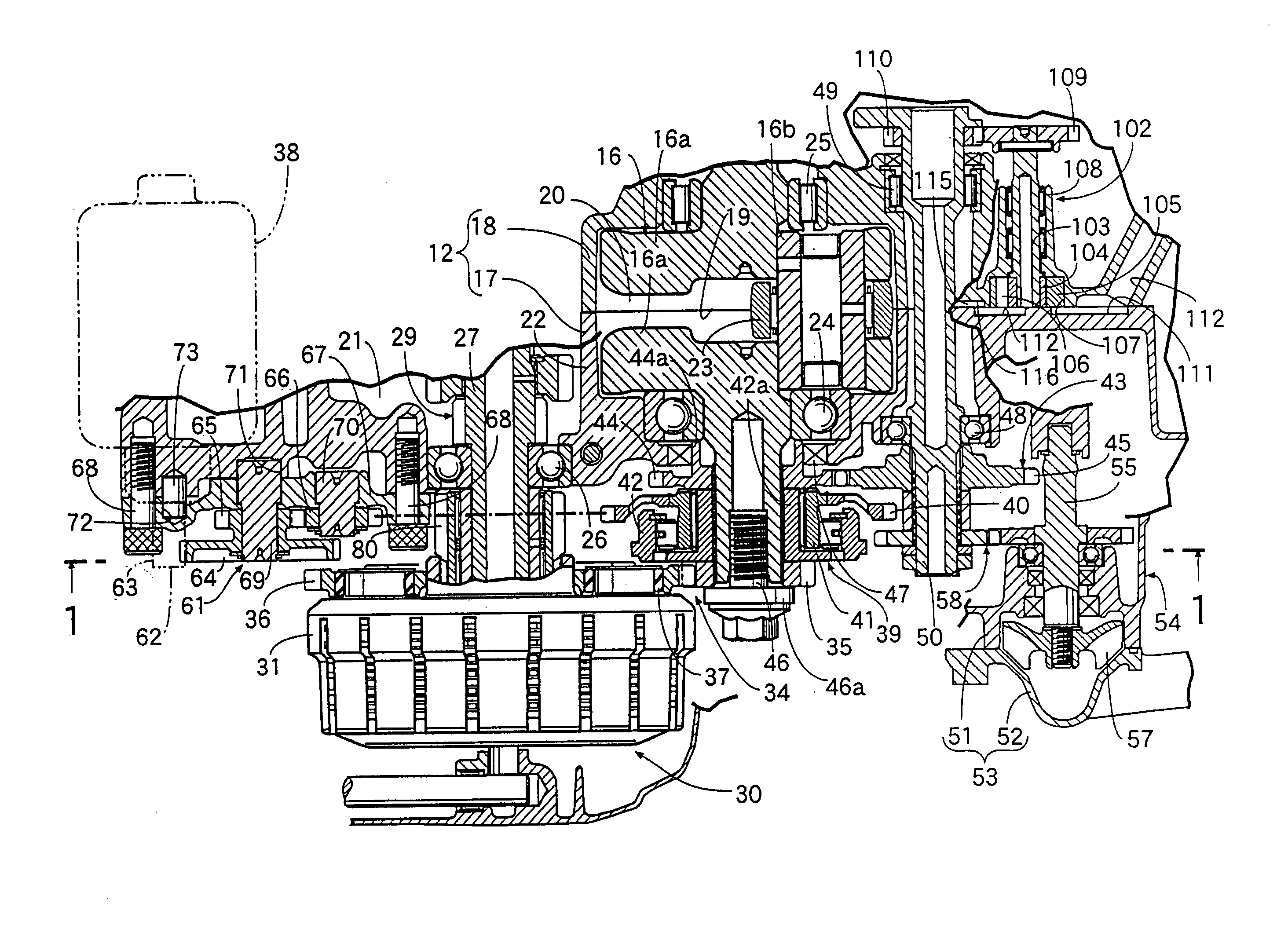
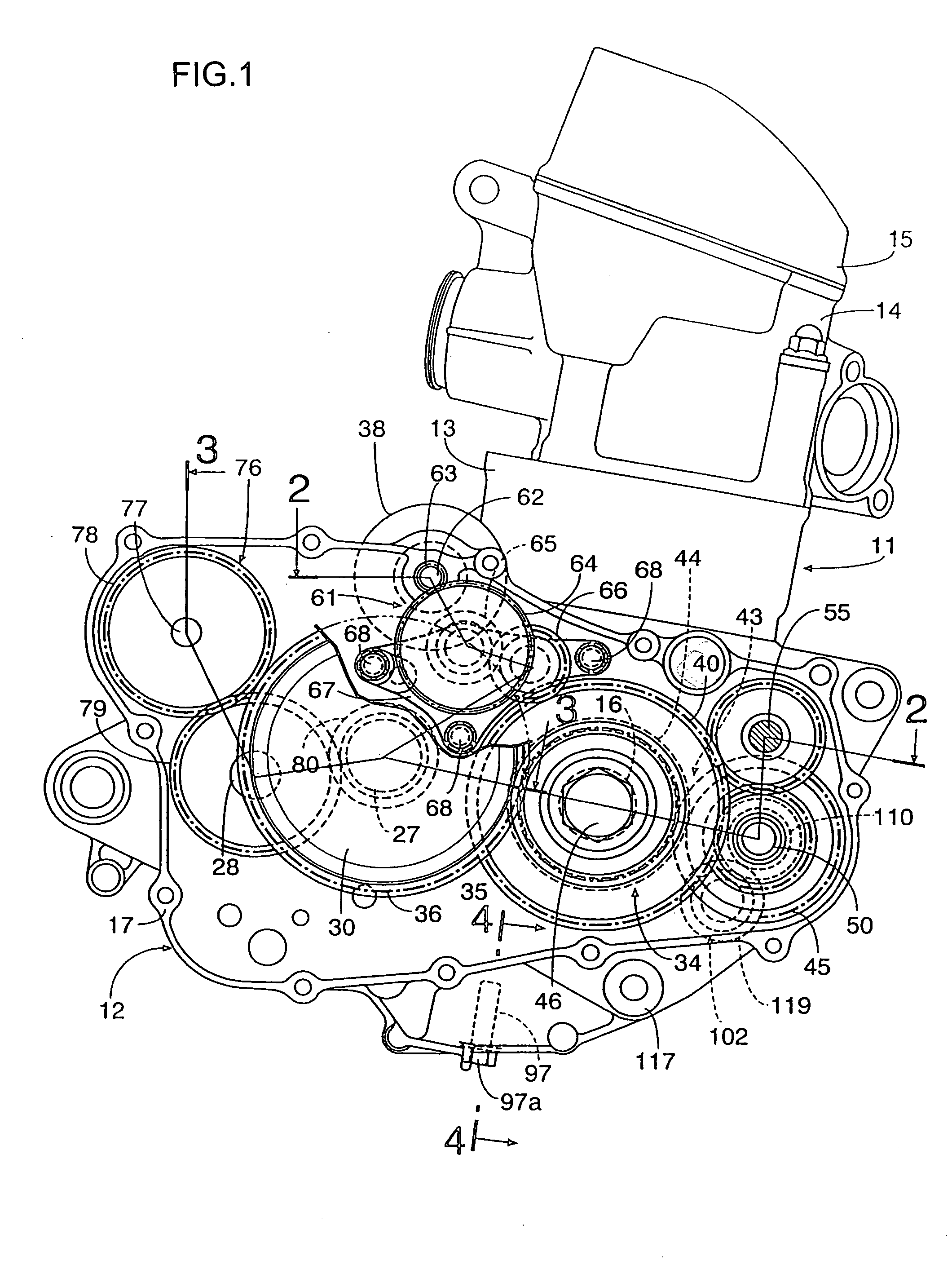
[0017] Referring to FIG. 1, a single-cylinder four-cycle engine that is adapted to be mounted on a vehicle such as a motorcycle is shown. The engine main body 11 comprises a crankcase 12, a cylinder block 13 coupled to the crankcase 12, a cylinder head 14 coupled to the cylinder block 13, and a head cover 15 coupled to the cylinder head 14.

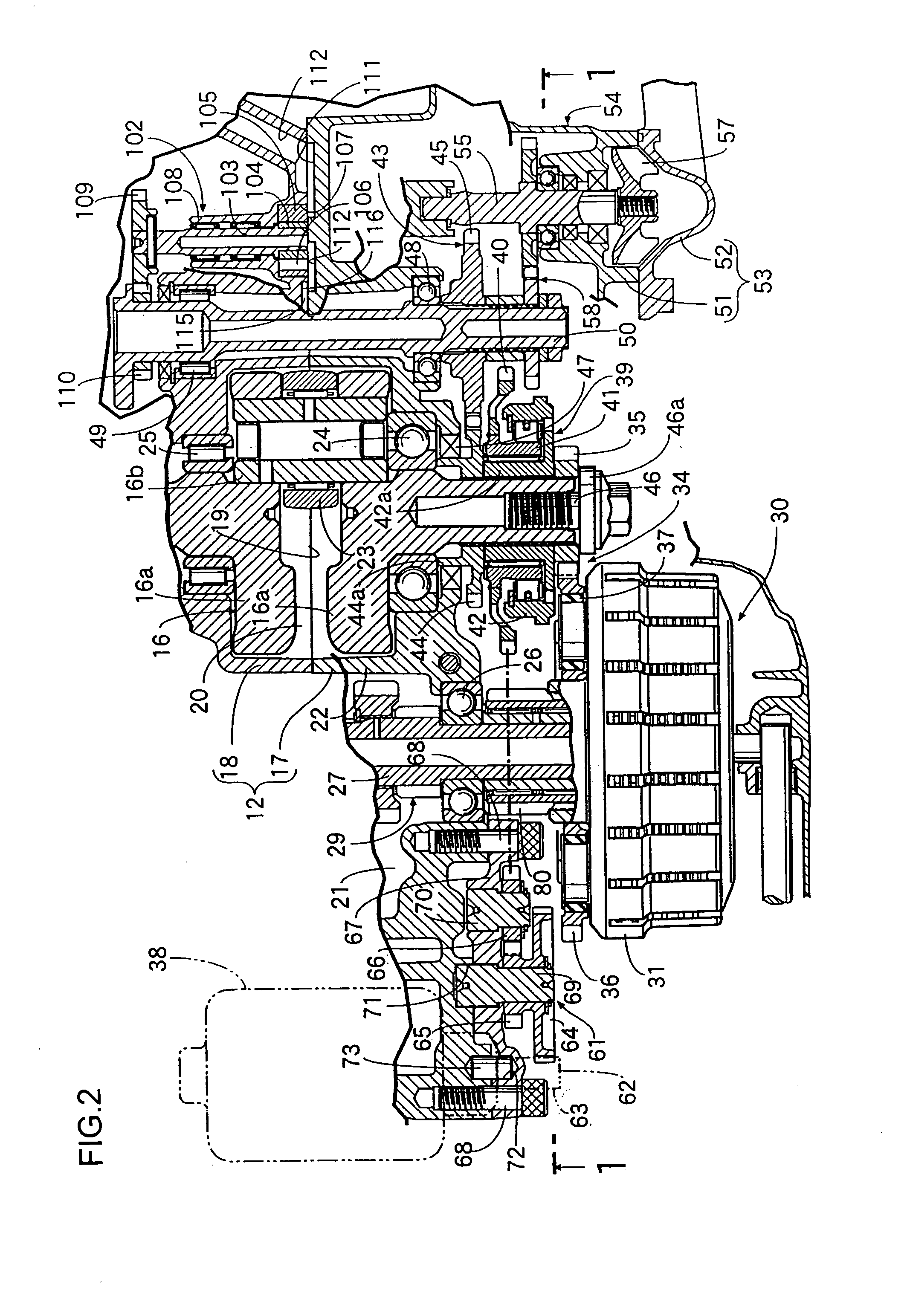
[0018] Referring to FIG. 2 also, the crankcase 12 for rotatably bearing a crankshaft 16 comprises a right case half 17 disposed on the right side at the time of mounting on the motorcycle, and a left case half 18 disposed on the left side at the time of mounting on the motorcycle. The case halves 17 and 18 are coupled to each other at a mating surface 19 along a plain surface orthogonal to the axis of the crankshaft 16 and are formed of an aluminum alloy. Moreover, a crank chamber 20 for containing an essential part of the crankshaft 16 and a transmission chamber 21 for containing a normally meshed type transmission are formed in the crankcase 12...


PUM


Abstract

The invention is directed at a device that reduces the size of an engine in the direction along the axis of a crankshaft. More specifically, it relates to an engine starting system in which a part of a starting power transmission gear train is provided between one end portion of a crankshaft rotatably borne on a crankcase and a starter motor mounted to the crankcase is covered from the outside by an accessory coupled to and operated in conjunction with the crankshaft.

Description

TECHNICAL FIELD [0001] The present invention relates to an engine starting system. More specifically, the invention relates to an arrangement of a starting power transmission. BACKGROUND OF THE INVENTION [0002] Starting systems are known. See, for example, Japanese Patent No. 2002-54540. [0003] In prior art starting systems, a part of the starting power transmission gear train is typically covered from the outside by a shift gear switching clutch that is coupled to and operated in conjunction with the crankshaft. In the prior art starting systems, the gears constituting a part of the starting power transmission gear train and covered with the clutch are borne in a center gear manner. Accordingly, the amount of outward projection of the clutch along the axis of the crankshaft is comparatively large, leading to an increase in the size of the engine, which is generally not desired. [0004] The present invention has been made in consideration of the above-mentioned drawback as well as ot...

Claims


Application Information

Patent Timeline
IPC IPC(8): F02B67/00F02B67/04F02N15/02
CPCF02N15/006Y10T74/137F02N15/02
Inventor TSUTSUMI, KOICHITAKAMATSU, HIDETOSHINAKAMICHI, KATSUHIROSUGIURA, HIROYUKI
Owner HONDA MOTOR CO LTD
Why Eureka
Eureka Blog
Learn More