Multi-directional switch

a multi-directional switch and switch body technology, applied in the direction of contact mechanisms, mechanical control devices, instruments, etc., can solve the problems of many processes, high cost of metal mold repair, and inability to repair metal molds for the plurality of central protruding portions, etc., to achieve low cost, easy repair, and reduced cost of assembling the multi-directional switch

Active Publication Date: 2005-02-24
ALPS ALPINE CO LTD
View PDF11 Cites 23 Cited by
  • Summary
  • Abstract
  • Description
  • Claims
  • Application Information

AI Technical Summary

Benefits of technology

[0009] Accordingly, the present invention is designed to solve the above-mentioned problems, it is an object of the present invention to provide a low-priced multi-directional switch that is capable of giving a good feeling of operation to an operating portion.
[0011] With such a structure, when the operating shaft rocks in one direction from a state in which the actuator abuts to the bottom portion of the cam, the actuator abutted to the bottom portion of the cam is moved to an upper side along a predetermined first inclined surface which corresponds to the rocking direction of the operating shaft, and then reaches the second inclined surface after exceeding the swelled step portion. As a result, in a step that the actuator exceeds the swelled step portion, a feeling of click can be given to the operating shaft. And then, only by assembling one cam in a predetermined position, a setting of all of feeling giving means (the swelled step portions) can be completed in one operation. Therefore, the assembling of the multi-directional switch is efficiently performed, and the cost of assembling the multi-directional switch can be reduced. Further, with a molding of this type of the cam, the metal mold can be easily repaired when the feeling of the click is adjusted, and it is possible to provide a low-priced metal mold. In addition, a repairing portion is constructed in a telescopic manner, it is possible to restore a shape of the metal mold in an original shape. Accordingly, it is possible to provide a low-priced multi-directional switch product compared to a conventional art.
[0012] Further, in the multi-directional switch of the present invention, the operating shaft is configured to be supported rockably and rotatably by the bearing. In the present invention, a feeling of click during a rocking of the multi-directional switch is implemented by a combination of the above-mentioned cam and actuator. Similarly, by forming a contact portion of the actuator in a spherical shape, the rotation of the operating shaft also becomes possible.
[0013] As described above, when the operating shaft is supported rockably and rotatably by the bearing, a switching of the contact can be performed by a rotation operation as well as the rocking operation of the operating shaft. As a result, it is possible to implement a multi-directional switch with a multifunction.

Problems solved by technology

As a result, there are problems in that many processes are required in assembling a switch and a high-priced switch is produced.
However, since the rubber seat is fabricated by a molding using a relatively large metal mold, in the case of adjusting the feeling of the click, the metal mold cannot be repaired for the plurality of the central protruding portions, and repairing the metal mold is costly.
As a result, it is impossible to sufficiently lower the fabrication cost of the switch.

Method used


Image

  • Multi-directional switch
  • Multi-directional switch
  • Multi-directional switch

Examples


Embodiment Construction

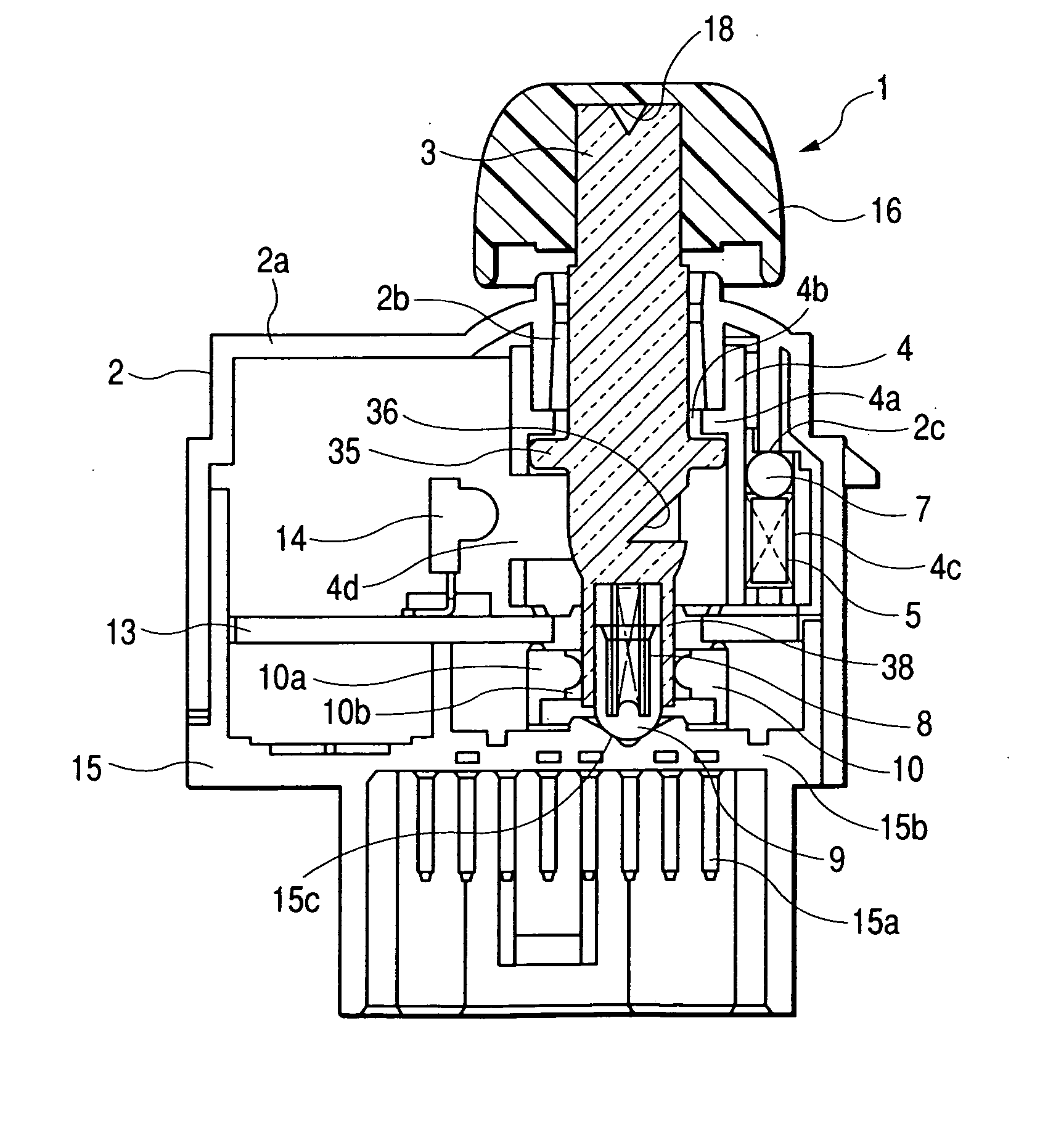
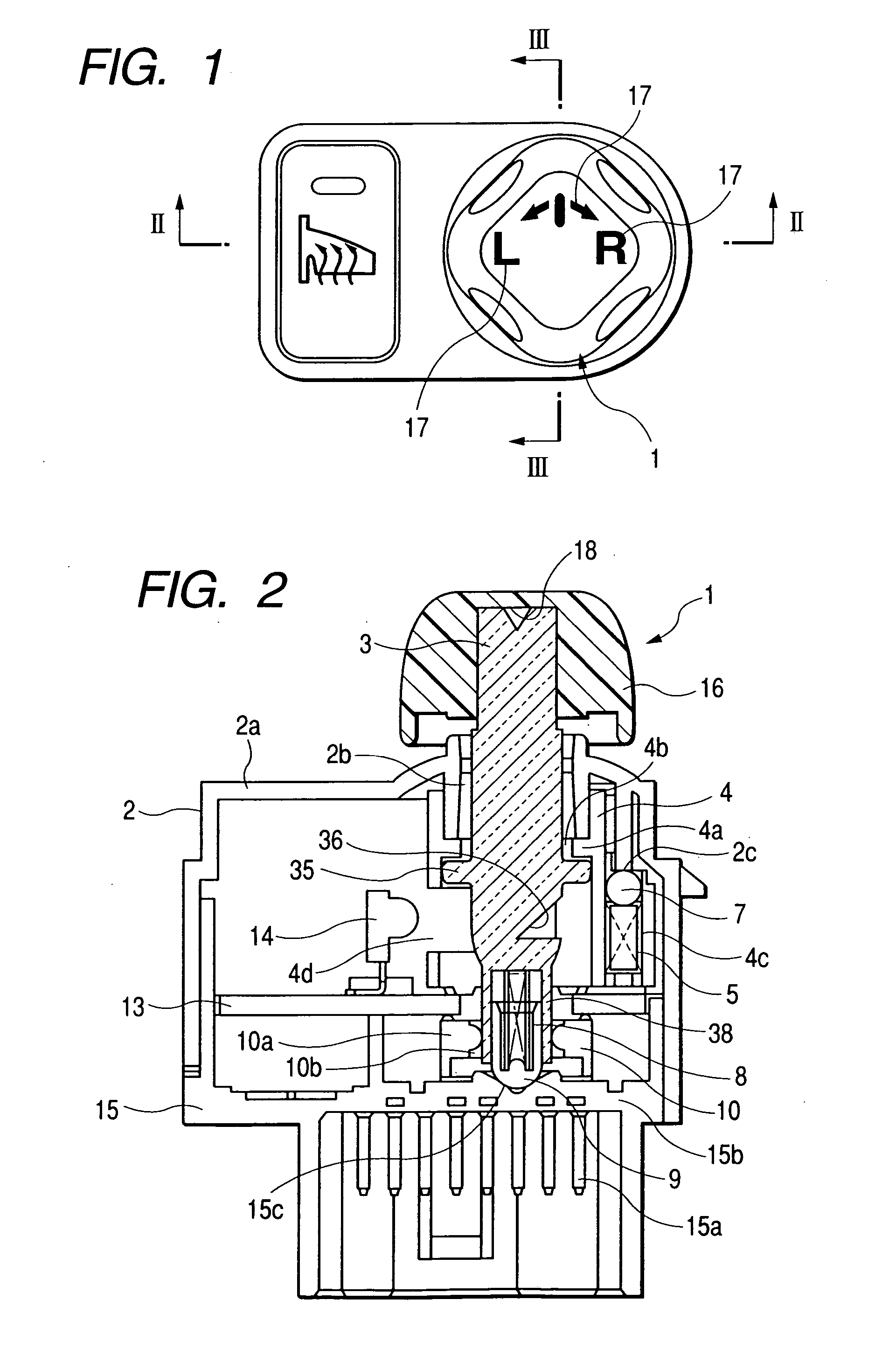
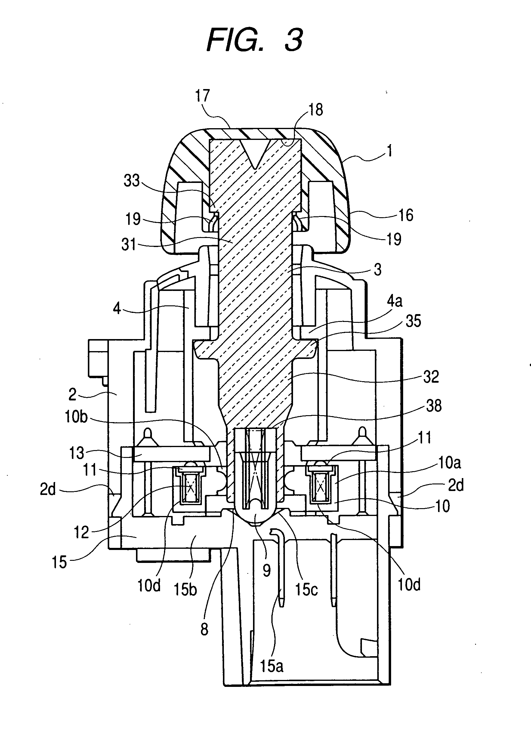
[0023] Hereinafter, an application of a multi-directional switch according to an embodiment of the present invention to a power mirror device that adjusts an angle of vision of a motor-driven side mirror for a vehicle will be described with reference to FIGS. 1 to 9.

[0024]FIG. 1 is a plan view of a multi-directional switch according to an embodiment, FIG. 2 is a cross-sectional view taken along the line II-II of FIG. 1, FIG. 3 is a cross-sectional view taken along the line III-III of FIG. 1, FIG. 4 is an exploded perspective view of the multi-directional switch according to the embodiment, FIG. 5 is an explanation view showing a structure of each portion of an operating shaft included in the multi-directional switch according to the embodiment, FIG. 6 is an explanation view showing a function of the operating shaft included in the multi-directional switch according to the embodiment, FIG. 7 is a plan view of a cam included in the multi-directional switch according to the embodiment...


PUM


Abstract

A multi-directional switch contains a bearing 4, an operating shaft 3 supported rockably by the bearing 4, and a cam 15c for giving a required feeling of operation to a rocking operation of the operating shaft 3. In the cam 15c, a spherical surface-shaped bottom portion 41 for holeing the operating shaft 3 in a non-operation position, first inclined surfaces 42, 43, 44 and 45 formed in a radial shape at an outer circumference of the bottom portion 41, and second inclined surfaces 46, 47, 48 and 49 formed in a radial shape at an outer circumference of the first inclined surfaces, are formed, and at the boundaries between the first inclined surfaces and the second inclined surfaces, swelled step portions 50, 51, 52 and 53 are formed, respectively.

Description

[0001] This application claims the benefit of priority to Japanese Patent Application No. 2003-201788 filed on Jul. 25, 2003, herein incorporated by reference. BACKGROUND OF THE INVENTION [0002] 1. Field of the Invention [0003] The present invention relates to a multi-directional switch used in a vehicle power mirror device, and more specifically, means for giving a required feeling of operation to an operation of an operating shaft. [0004] 2. Description of the Related Art [0005] As means for giving a feeling of operation such as a click to an operating portion of a multi-directional switch, means which allows a movable contact of a dome shape, formed of a metal plate, to be elastically deformed in an operating portion and transfers to the operating portion a feeling when the movable contact is elastically deformed (See Japanese Unexamined Patent Application Publication No. 2002-170461 (FIGS. 1 and 2)), means which allows a movable contact provided in a central protruding portion o...

Claims


Application Information

Patent Timeline
Patent Type & Authority Applications(United States)
IPC IPC(8): H01H25/04G05G1/08G05G5/03H01H23/00
CPCB60K37/06B60K2350/102G05G1/08G05G5/03H01H2025/043H01H2219/062H01H2300/01H01H2300/012H01H25/04B60K2370/126B60K2370/158H01H23/00
Inventor GOTOH, KAZUNORI
Owner ALPS ALPINE CO LTD
Why Eureka
Try Eureka