Grooved angled tray for ring-handled surgical instruments

a technology for surgical instruments and trays, which is applied in the field of trays for surgical instruments, can solve the problems of inability to provide a compact, efficient, and convenient way to space and stack ring-handled surgical instruments, and achieve the effect of convenient grasping and facilitating counting of ringed instruments

Inactive Publication Date: 2005-02-24
PULSIFER JANICE
View PDF38 Cites 20 Cited by
  • Summary
  • Abstract
  • Description
  • Claims
  • Application Information

AI Technical Summary

Benefits of technology

[0018] It is another aspect of the invention to provide a grooved angled tray for ring-handled surgical instruments that facilitates counting of the ringed instruments during surgical procedures.
[0019] It is a further aspect of the invention to provide a grooved angled tray for ring-handled surgical instruments that provides a stable surface upon which to mount the instruments.
[0020] It is an additional aspect of the invention to provide a grooved angled tray for ring-handled surgical instruments that allows the instruments to be easily grasped at the lower portions of the instruments prior to transfer into the doctor's hands.
[0021] It is an aspect of the invention to provide improved elements and arrangements thereof for the purposes described which is inexpensive, dependable and fully effective in accomplishing its intended purposes.

Problems solved by technology

Sometimes, however, before and during use of the surgical instruments, the instruments supported on the rolled towel can become mixed and disorganized.
Accordingly, the instruments become more difficult to count, select and handle prior to actual use of the instruments, or while the instruments are assembled prior to sterilization.
A few instrument stands, racks and trays are recognized in the prior art, but none provide a compact, inexpensive, and efficient manner in which to space and stack ring-handled surgical instruments.

Method used


Image

  • Grooved angled tray for ring-handled surgical instruments
  • Grooved angled tray for ring-handled surgical instruments
  • Grooved angled tray for ring-handled surgical instruments

Examples


Embodiment Construction

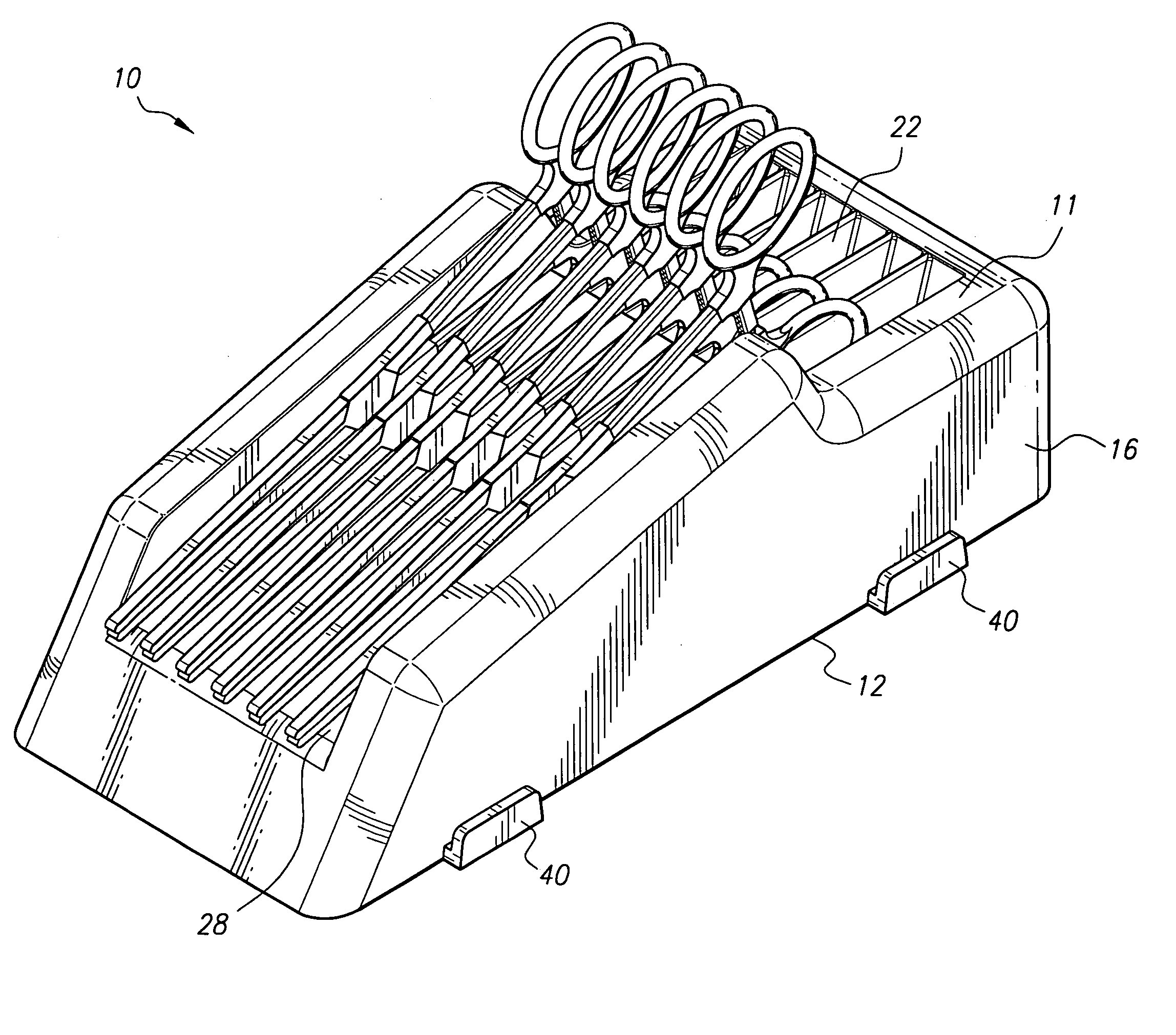
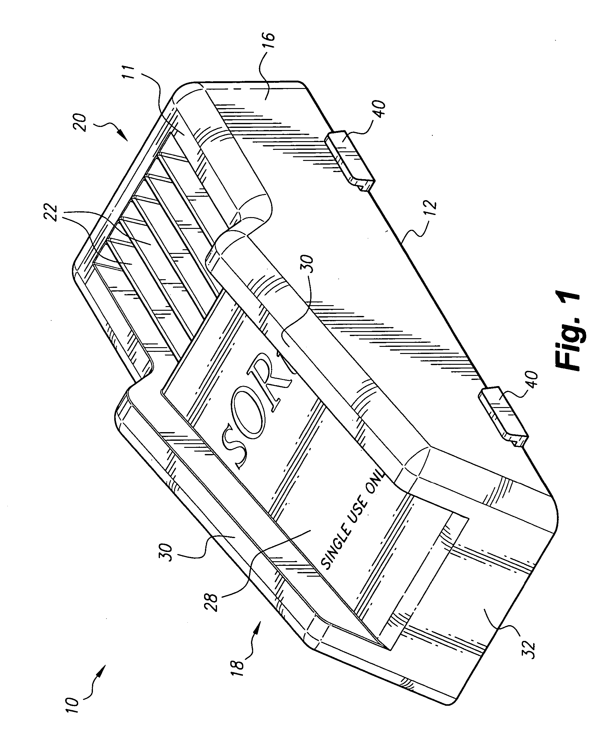
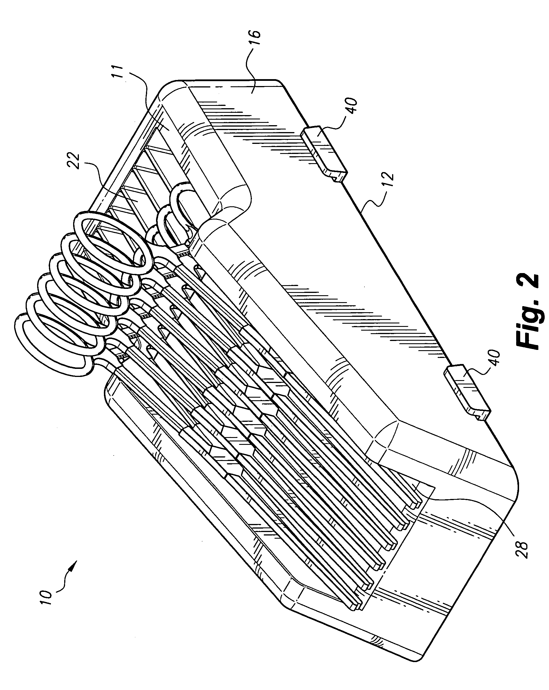
[0030] The present invention relates to a grooved angled tray for ring-handled surgical instruments, designated generally as 10 in the drawings. The tray 10 can be made in various shapes and sizes. The tray 10 includes a horizontal top 11, a horizontal base 12 parallel to the horizontal top 11, a sloped front wall 18, a rear wall 20, and parallel, opposing sidewalls 16. The rear wall 20 is vertical and extends normal to the top 11 and base 12. The front wall 18 slopes downward and extends to the base 12. The horizontal top 11 and the front wall 18 provide space into which ring-handled instruments are placed.

[0031] Referring first to FIG. 1, the tray 10 is shown with grooves 22 situated within the horizontal top 11 and an inclined ramp 28 along the front wall 18. The horizontal top 11 is disposed lower than the front wall 18. The grooves 22 in the horizontal top 11 allow for placement of a portion of the ring handles of the ring-handled instruments. The front wall 18 includes an inc...


PUM


Abstract

The grooved angled tray for ring-handled surgical instruments includes a horizontal top, a horizontal base that is disposed parallel to the horizontal top, a front wall, a rear wall, and a set of parallel sidewalls. The front wall is inclined and slopes outward from the top. The horizontal top and the front wall are adapted to hold and isolate a variety of ring-handled instruments. The horizontal top is provided with a series of grooves that receive the ring handles of the ring-handled instruments. The front wall has an inclined ramp that allows lower portions of the ring-handled instruments to rest. In another embodiment, the horizontal top and front wall are together provided with a series of grooves that receive the ring handles and the lower portions of the ring-handled instruments.

Description

CROSS-REFERENCE TO RELATED APPLICATION [0001] This application claims the benefit of U.S. Provisional Patent Application Ser. No. 60 / 496,928, filed Aug. 22, 2003.BACKGROUND OF THE INVENTION [0002] 1. Field of the Invention [0003] The present invention relates to a device for organizing surgical instruments, and particularly, to a surgical instrument tray useful for organizing ring-handled instruments. [0004] 2. Description of the Related Art [0005] Ring-handled surgical instruments are normally separated and organized during surgical procedures and also prior to sterilization by being laid out on rolled-up cotton towels. The rolled-up cotton towels, which may have their outside edges taped, support the instruments such that the instruments can be more easily counted, selected and handled by a nurse or surgical technician. Generally, the technician or nurse grips the instruments on the lower portions of the instruments and places the ring handles of the instrument directly into the d...

Claims


Application Information

Patent Timeline
Patent Type & Authority Applications(United States)
IPC IPC(8): A61B19/02
CPCA61B19/0256A61B2019/0259A61B2019/0258A61B19/0271A61B50/20A61B50/22A61B50/24A61B50/33
Inventor PULSIFER, JANICE
Owner PULSIFER JANICE
Why Eureka
Try Eureka