
Display panel and display device

A display panel and display device technology, which is applied in the direction of instruments, semiconductor devices, optics, etc., can solve problems such as unfavorable counting, time-consuming and labor-intensive mirror inspection process, and difficulty in improving the production efficiency of display equipment.

Active Publication Date: 2019-03-26
SHANGHAI AVIC OPTOELECTRONICS
View PDF5 Cites 18 Cited by
  • Summary
  • Abstract
  • Description
  • Claims
  • Application Information

AI Technical Summary

Problems solved by technology

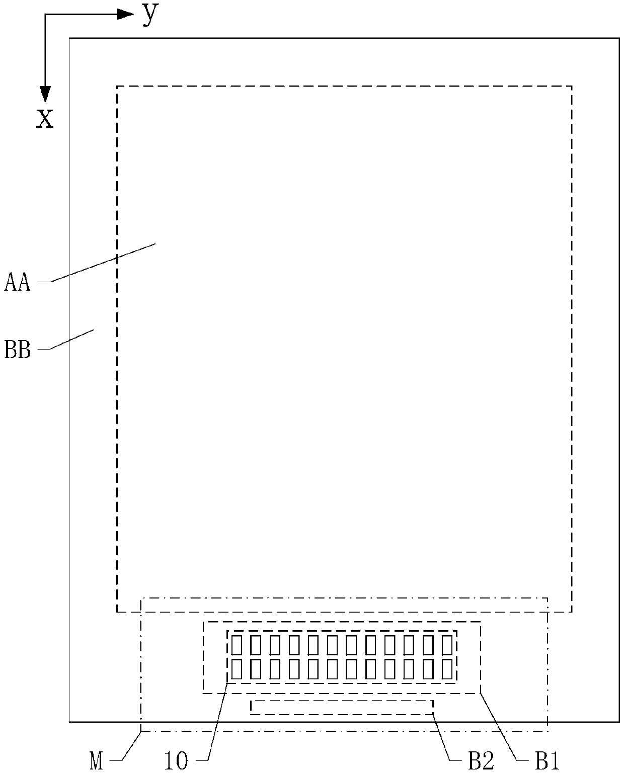
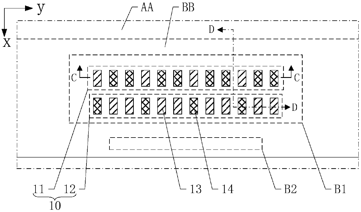
[0004] However, when microscopically inspecting the bonding pads for short circuits and foreign matter defects, it is often necessary to increase the magnification of the microscope, and when counting the bonding pads to determine the location of the abnormality, the magnification of the microscope has to be lowered , otherwise the number of bonded pads in the same field of view is small, which is not conducive to counting. Switching the magnification back and forth in this way makes the mirror inspection process time-consuming and laborious, and it is difficult to improve the production efficiency of the display device.

Method used


Image

  • Display panel and display device
  • Display panel and display device
  • Display panel and display device

Examples


Embodiment Construction

[0032] Various exemplary embodiments of the present invention will now be described in detail with reference to the accompanying drawings. It should be noted that the relative arrangements of components and steps, numerical expressions and numerical values ​​set forth in these embodiments do not limit the scope of the present invention unless specifically stated otherwise.

[0033] The following description of at least one exemplary embodiment is merely illustrative in nature and in no way taken as limiting the invention, its application or uses.

[0034] Techniques, methods and devices known to those of ordinary skill in the relevant art may not be discussed in detail, but where appropriate, such techniques, methods and devices should be considered part of the description.

[0035] In all examples shown and discussed herein, any specific values ​​should be construed as exemplary only, and not as limitations. Therefore, other instances of the exemplary embodiment may have dif...


PUM


Abstract

The invention discloses a display panel and a display device. The display panel comprises a display area and a non-display area arranged around the display area, wherein the non-display area includesa first binding area and a second binding area; the first binding area includes at least one output unit, the output unit includes a first bonding pad group and a second bonding pad group, the first bonding pad group and the second bonding pad group are arranged in a first direction, and both the first bonding pad group and the second bonding pad group include a plurality of first output bonding pads and a plurality of second output bonding pads which are arranged in a second direction; the first output bonding pads and the second output bonding pads are arranged in different layers; in the first bonding pad group, two adjacent first output bonding pads are provided with at least two second output bonding pads therebetween, and in the second bonding pad group, two adjacent second output bonding pads are provided with at least two first output bonding pads therebetween. Compared with the prior art, the output bonding pads can be counted more conveniently when microscopic examination iscarried out, thereby being conducive to improving the abnormal bonding pad detection accuracy.

Description

technical field [0001] The present invention relates to the field of display technology, and more particularly, to a display panel and a display device. Background technique [0002] With the continuous development of display technology, the display screen has gradually developed from the original cathode ray tube (Cathode Ray Tube, CRT) display to the popular liquid crystal display (Liquid Crystal Display, LCD) and organic light emitting display (Organic Light Display) in recent years. Emitting Diode, OLED) and so on. At the same time, with people's continuous pursuit of visual effects, continuously narrowing the frame of the display screen and increasing its screen-to-body ratio has become an important research direction of the current display technology. [0003] Due to the narrowing of the frame of the display screen, the size of the driving module used to drive the screen display of the display screen needs to be continuously reduced, and even integrated into the same ...

Claims


Application Information

Patent Timeline
Patent Type & Authority Applications(China)
IPC IPC(8): G02F1/1345H01L27/32
CPCG02F1/13452G02F1/13458H10K59/10
Inventor 金慧俊
Owner SHANGHAI AVIC OPTOELECTRONICS
Learn More