Scalpel blade remover

a blade and blade technology, applied in the field of blade removers, can solve the problems of inconvenient use, inconvenient use, and operator injury, and achieve the effect of preventing subsequent use and ensuring the number of blades

Active Publication Date: 2008-07-15
QLICKSMART PTY LTD
View PDF8 Cites 19 Cited by
  • Summary
  • Abstract
  • Description
  • Claims
  • Application Information

AI Technical Summary

Benefits of technology

[0021]The scalpel blade remover of this invention has the advantages of those described in U.S. Pat. No. 5,699,908 and U.S. Pat. No. 5,875,533, namely the blade can be removed safely and automatically by moving the scalpel handle single-handedly in a simple in-out movement along a linear path. However, unlike the prior art scalpel blade removers, the scalpel blade remover of this invention is single use only, and the removed blade is encapsulated between the housing and actuator. The scalpel blade remover of this invention can therefore be used in sterile environments, and facilitates the counting of used blades.
[0039]Advantageously, the scalpel blade remover of the present invention permits a variety of blade types and shapes to be removed from a large number of handle sizes and makes. In a preferred configuration, the scalpel blade remover of the present invention resists the partial removal of a scalpel blade and subsequent jamming. Thus, the scalpel blade remover is less likely to be rendered inoperable as a result of a jammed blade. The scalpel blade remover of the present invention retains the scalpel blade in the housing whereby its subsequent use is prevented. Thus, the number of blades may be readily accounted for by simply counting the number of used scalpel blade removers having a blade therein. As described above, the scalpel blade removers may allow the scalpel blade to be seen through the materials of construction of the housing.

Problems solved by technology

Manual removal of the blade can be hazardous.
During the manipulation of the blade the operator is put at risk of being cut on the sharp blade.
With the ever-increasing spread of blood transmitted diseases such as AIDS and hepatitis, any accidental injury from the blade can result in infection or contamination.
Most of these require two-handed operation, or bending or twisting of the scalpel, rendering them dangerous and / or awkward to use.
As the devices of U.S. Pat. No. 5,699,908 and U.S. Pat. No. 5,875,533 are designed for repeated use, and since they store multiple blades within a single container, they render it difficult to account accurately for all blades used during a surgical procedure.
This is not readily possible with multiple blades being stored within a sharps container unless the container is emptied prior to each sterilisation.

Method used


Image

  • Scalpel blade remover
  • Scalpel blade remover
  • Scalpel blade remover

Examples


Embodiment Construction

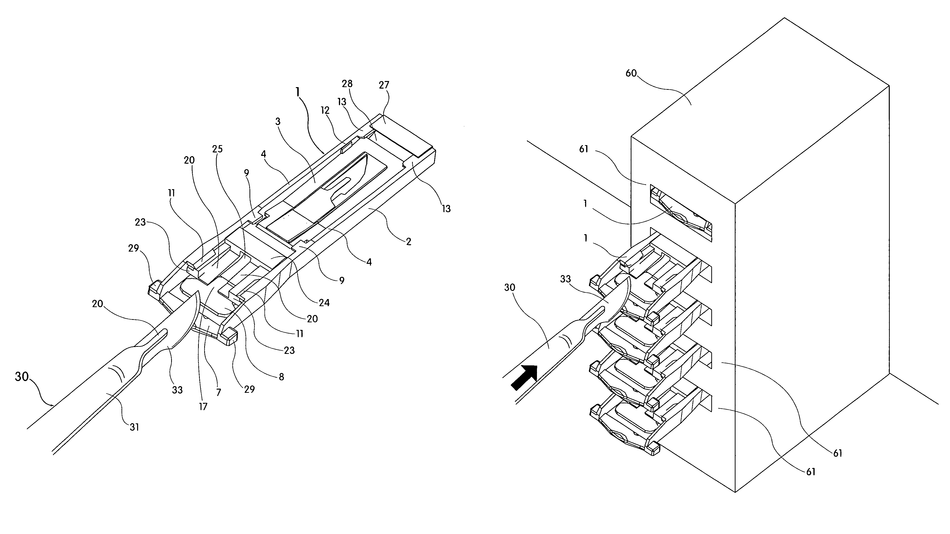
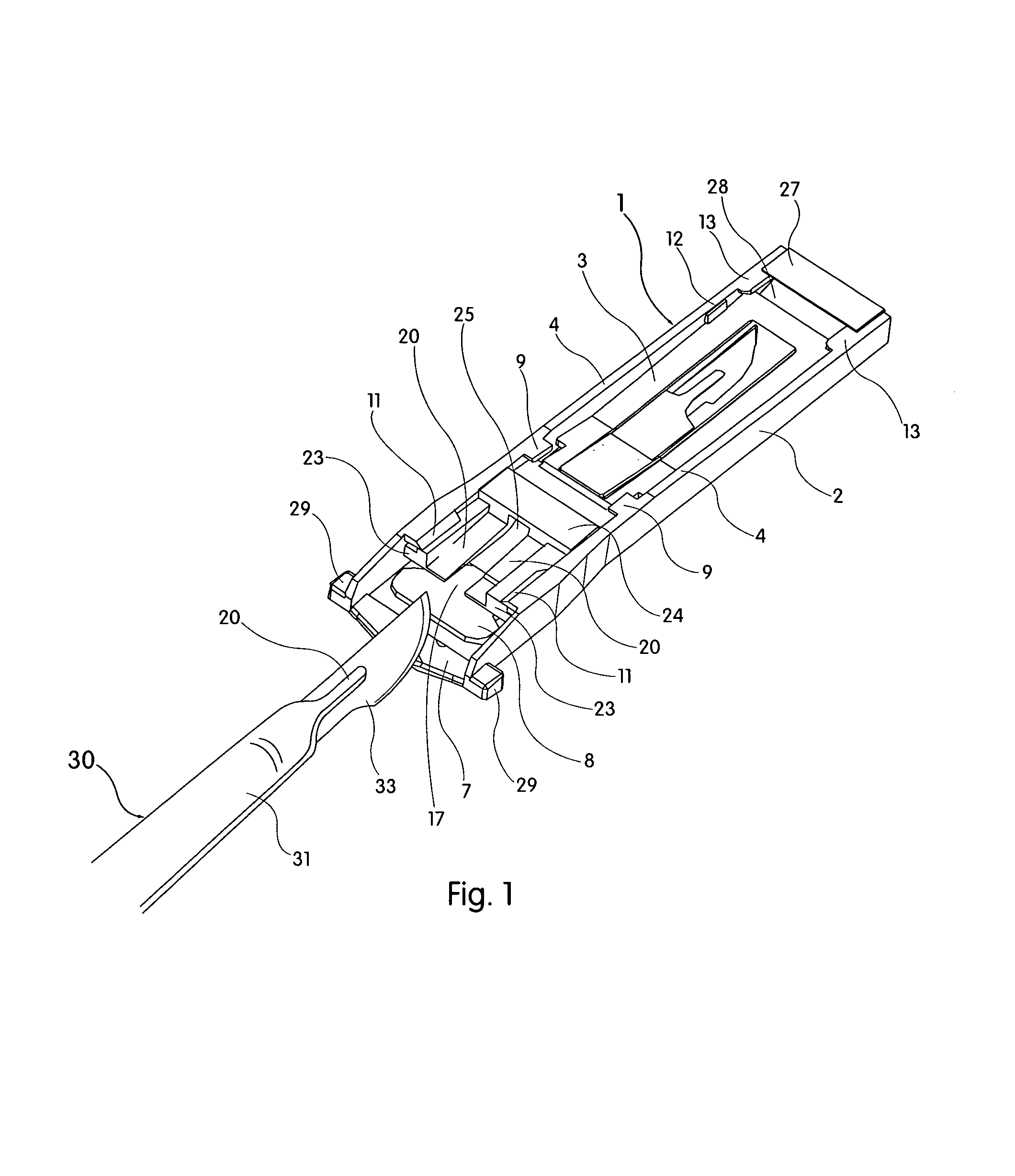
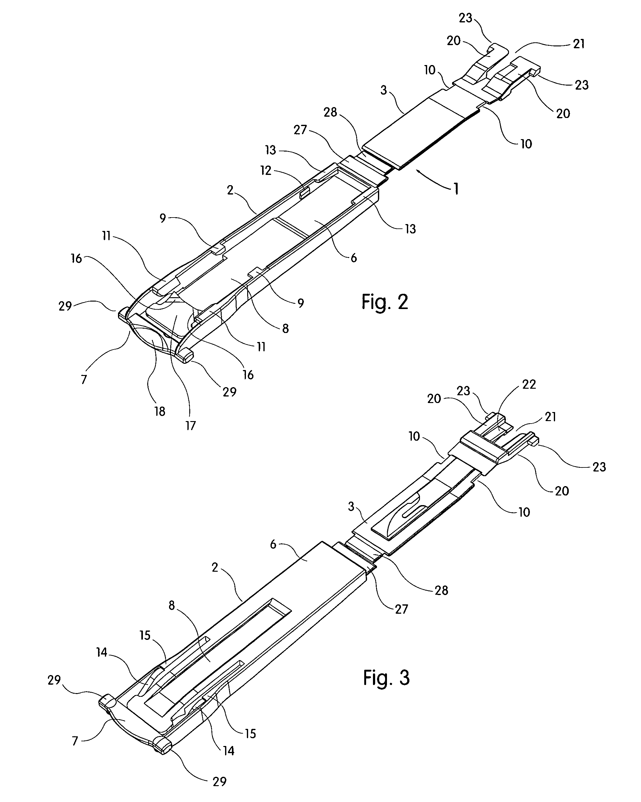
[0061]FIG. 1 shows a scalpel blade remover 1 comprising two main parts, namely a housing 2 and an actuator 3. In use, the actuator 3 is disposed within the housing 2. The scalpel blade remover 1 will be described with reference to its horizontal orientation as shown in the drawings. However, the blade remover can be used vertically or in any other suitable orientation, and the interpretation of the terms such as “upper”, “lower”, “above” and “below” as used herein is to be varied accordingly.

[0062]The housing 2 has two opposed sidewalls 4, an end wall 5 at one end (hereafter referred to as the “distal end”), a base 6 spanning between the side walls for part of their length from the end wall, and a bridge or brace 7 which is co-planar with the base and extends between the sidewalls 4 at the other end (hereafter referred to as the “proximal end”). The base 6 has a cantilevered portion which extends towards the brace 7 and forms a leaf spring 8.

[0063]Inwardly extending retaining lugs 9...


PUM

PropertyMeasurementUnit
flexibleaaaaaaaaaa
movementaaaaaaaaaa
forceaaaaaaaaaa

Abstract

A single-use scalpel blade remover (1) removes a blade (33) from a tang (32) of a scalpel (30) and captures it, in a single-handed operation. The remover (1) comprises a housing (2) having a detent (16), and an actuator (3) which is operatively juxtaposed with the housing (2) and moveable alongside the housing in a forward direction from a proximal position (whereat an opening is formed between the proximal ends of the actuator and the housing) to a distal position (whereat the detent (16) engages the proximal end of the actuator). The blade remover (1) also includes a cam-operated mechanism (14,23,20) for automatically separating the heel of the blade (33) from the tang (32) as the actuator (3) is moved to the distal position. In use, the blade (33) on the tang (32) is inserted in the opening and the actuator is pushed forward by the tang to its distal position, whereupon the detent (16) engages the proximal end of the actuator (3) and retains it in its distal position and prevents rearward movement of the blade (33). As the heel has been separated from the tang (32), upon withdrawal of the tang from the scalpel blade remover (1), the blade (33) is stripped from the tang and retained captively between the actuator (3) and the housing (2).

Description

CROSS-REFERENCE TO RELATED APPLICATION[0001]This application is a Continuation of International Application No. PCT / AU2004 / 000533, filed Apr. 23, 2004, which was published in the English language on Nov. 4, 2004, under International Publication No. WO 2004 / 093706 A1 and the disclosure of which is incorporated herein by reference.[0002]The present invention relates to a scalpel blade remover. In particular, the present invention relates to a scalpel blade remover that enables a blade to be removed from a scalpel and retained in the remover.BACKGROUND ART[0003]A conventional surgical scalpel typically comprises a reusable, sterilisable elongate handle or haft onto which a replaceable slotted blade is mounted. At the distal end of the handle is a tang that normally includes opposed grooves or channels to receive the blade. Generally the tang is a narrow extension of the handle. The blade has a slot extending longitudinally, which slot has a portion of sufficient width to be received ov...

Claims


Application Information

Patent Timeline
Patent Type & Authority Patents(United States)
IPC IPC(8): B65D83/10A61B17/3217A61B17/32A61B19/02A61B46/23
CPCA61B17/3217A61B19/0256A61B19/0271Y10T29/53683A61B2019/4868A61B2019/4873A61B2017/00902A61B50/20A61B50/33A61B2090/0813A61B2090/0814
Inventor HENRY, ROBERT ANTHONY NEVILLE
Owner QLICKSMART PTY LTD
Why Eureka
Try Eureka