Machining control method for wire-cut electric discharge machine

Inactive Publication Date: 2005-02-24
FANUC LTD
View PDF2 Cites 10 Cited by
  • Summary
  • Abstract
  • Description
  • Claims
  • Application Information

AI Technical Summary

Benefits of technology

[0015] According to the present invention, the number of electric discharge pulses is uniform, so that the machined surface can enjoy uniform surface roughness. In consequence, uniform roughness can be obtained as required for the e

Problems solved by technology

If this method is used in actual finish machining, however, expected machining shapes sometimes may fail to be ensured in the vicinity of corner portions, in particular.
In some cases, therefore, a gap between the wire and the workpiece may be too wide to cause electric discharge, and the surface may fail to be finished.
In this case, the surface cannot be finished, and besides, machining must be stopped inevitably.
Also in this control method, electric discharge cannot be enjoyed at wide-gap portions, and the axis is fed with a short circuit at narrow-gap portions.
Thus, uniform surface roughness cannot be secured for an entire machin

Method used


Image

  • Machining control method for wire-cut electric discharge machine
  • Machining control method for wire-cut electric discharge machine
  • Machining control method for wire-cut electric discharge machine

Examples


first embodiment

[0034] First, the finish machining is started based on conventional axis feed speed constant control. Based on the machining programs, as in the conventional case, the movement commands to the axes are obtained every control period. According to the present invention, moreover, a path correction process shown in FIG. 5 is carried out.

[0035]FIG. 5 is a flowchart showing the path correction process according to the first embodiment of the invention. The processor 11 reads an electric discharge pulse number N(t) from the electric discharge pulse counter circuit 21 and then resets a counter for counting the electric discharge pulses (Step 100). By multiplying by a gain G1 a value obtained by subtracting the read electric discharge pulse number N(t) from a preset target electric discharge pulse number Ng, a correction value ΔP1(t) is obtained (Step 101).

[0036] Then, the direction normal to the path of movement of the wire electrode is obtained in accordance with the movement command tha...

second embodiment

[0042] In the case of the second embodiment, as described above, the correction value ΔP2(t) for the movement command is proportional to the value that is obtained by adding up the deviations between the detected electric discharge pulse number N(t) and the target electric discharge pulse number Ng. Therefore, the correction value ΔP2(t) never changes suddenly but smoothly, so that satisfactory machining stability can be obtained, and the machined surface can enjoy uniform roughness.

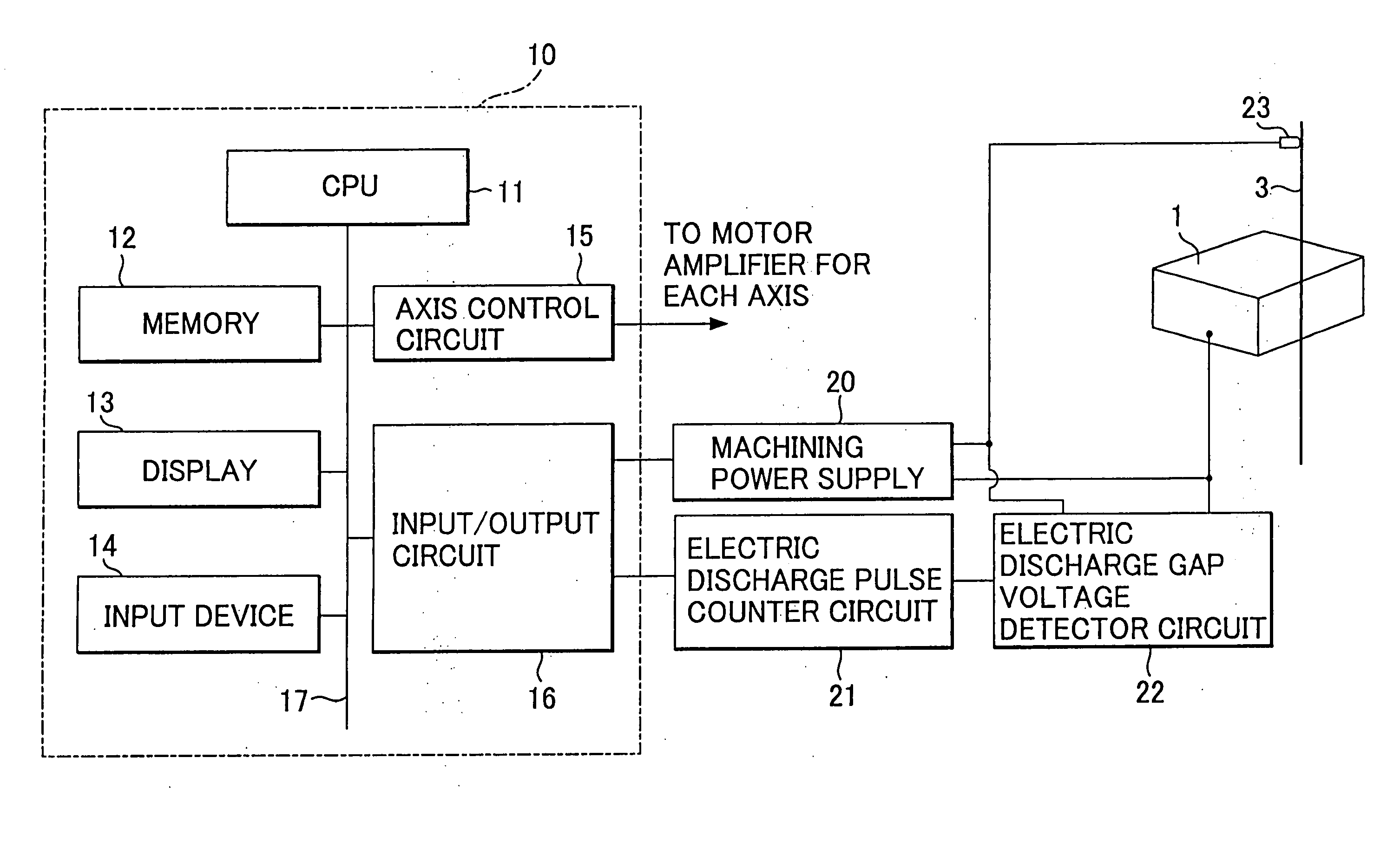
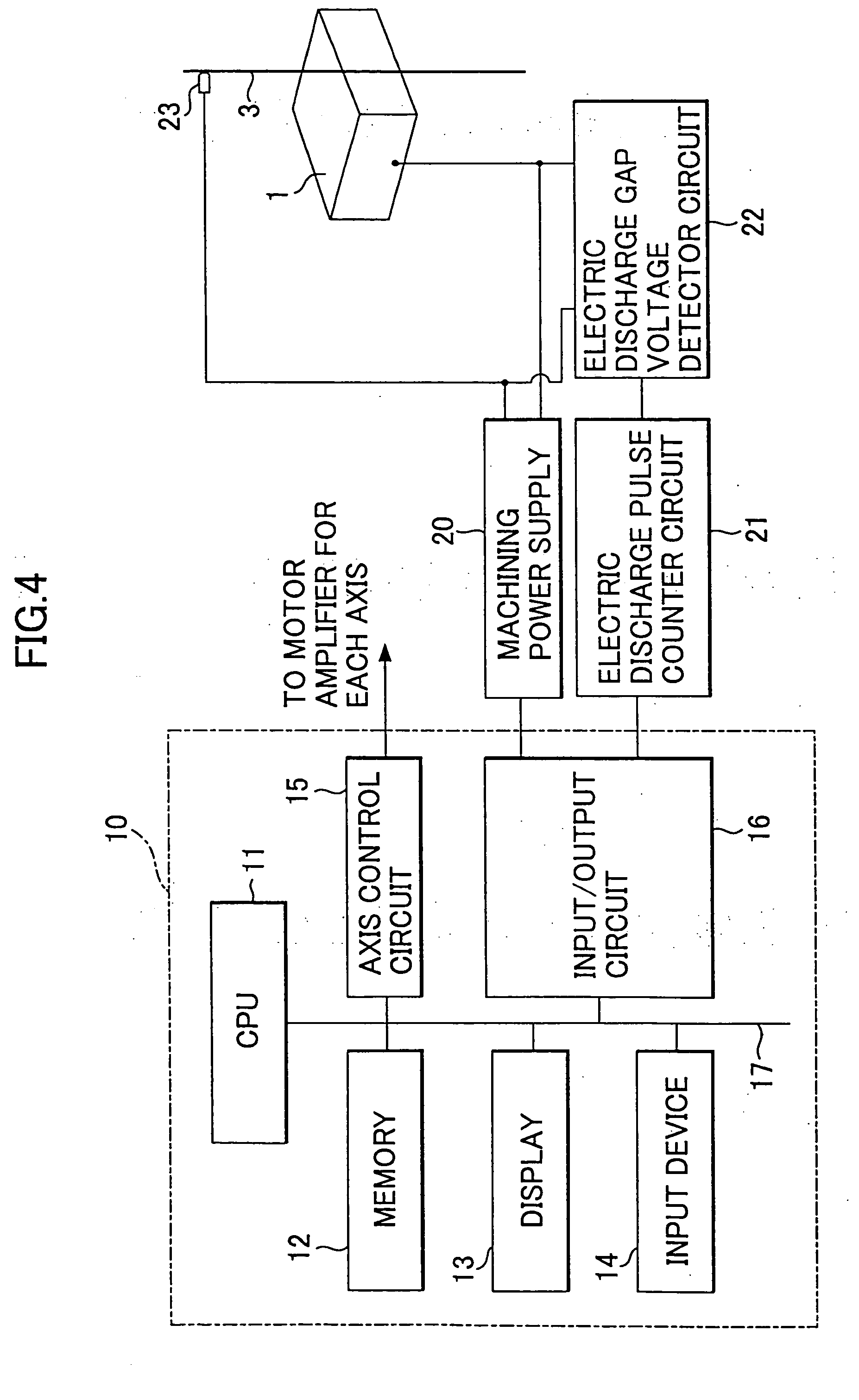
[0043]FIG. 7 is a flowchart showing a path correction process according to a third embodiment of the present invention. In this third embodiment, control is carried out with based on an average machining voltage, not on an electric discharge pulse number. In carrying out the third embodiment, the electric discharge pulse counter circuit 21 shown in FIG. 4 is replaced with an average machining voltage calculator circuit.

[0044] The processor 11 reads an average machining voltage V(t) from the average mach...

third embodiment

[0046] In the case of the third embodiment, as described above, the correction value ΔP3(t) for the movement command is proportional to the value that is obtained by adding up the deviations between the detected average machining voltage V(t) and the target average machining voltage Vg. Therefore, the correction value ΔP3(t) never changes suddenly, so that stable machining voltage can obtained. Thus, even if the machining voltage must be used in place of the electric discharge pulse number in consideration of special circumstances, definite effects, such as good machining stability and uniform surface roughness, can be enjoyed.

[0047] In each of the embodiments described herein, the normal direction is obtained in Step 102, 203 or 303. Alternatively, however, an offset process may be carried out to move the wire electrode 3 relatively to the workpiece 1 along the path instructed by the machining program with a given gap between the electrode and the workpiece. In this offset process,...


PUM

PropertyMeasurementUnit
Speedaaaaaaaaaa

Abstract

The number of electric discharge pulses is detected every given period. A deviation between the detected number and a target number of electric discharge pulses is obtained. Based on the obtained deviation, a correction value for the correction of a machining path in a direction normal to the machining path is calculated, whereby a corrected path is obtained. A wire electrode is moved relatively to a workpiece along the corrected path.

Description

BACKGROUND OF THE INVENTION [0001] 1. Field of the Invention [0002] The present invention relates to a machining control method for controlling axis feed, capable of ensuring stable finish machining. [0003] 2. Description of the Related Art [0004] In a known axis feed control method for finish machining, a machining characteristic value, such as the number of electric discharge pulses between a wire and a workpiece or machining voltage, is detected to control an axis feed speed so that the machining characteristic value agrees with a target value, thereby controlling an axis feed along a predetermined path. This control method is intended to obtain a fixed machining groove width after machining is finished. If this method is used in actual finish machining, however, expected machining shapes sometimes may fail to be ensured in the vicinity of corner portions, in particular. [0005] If a workpiece 1 involves a portion that is poor in shape accuracy, as shown in FIG. 1A, a given offset...

Claims


Application Information

Patent Timeline
IPC IPC(8): B23H7/02B23H7/04B23H7/06
CPCB23H7/065B23H7/04
Inventor KAWAHARA, AKIYOSHIFURUTA, TOMOYUKI
Owner FANUC LTD
Why Eureka
Try Eureka