Power management unit for use in portable applications

a power management unit and portable technology, applied in the direction of electric variable regulation, process and machine control, instruments, etc., can solve the problems of significant difficulty in integrating bipolar elements with other cmos circuit elements, and increase in power dissipation

Active Publication Date: 2005-02-24
AVAGO TECH INT SALES PTE LTD
View PDF3 Cites 35 Cited by
  • Summary
  • Abstract
  • Description
  • Claims
  • Application Information

AI Technical Summary

Benefits of technology

The present invention is directed to a power management unit for use in portable applications that substantially obviates one or more of the problems and disadvantages of the related art.

Problems solved by technology

Power management in portable electronic systems, such as cellular phone, portable PDAs, laptops, etc. is an important issue, as consumers increasingly demand longer times between recharging.
However, the use of bipolar technology presents difficulties with integrating the bipolar elements with other CMOS circuit elements.
The drawback of such an approach is an increase in power dissipation because the whole branch cannot be powered down.
In particular, if every circuit has all the functionality of breakdown protection, the power dissipation is significantly increased.
This is particularly a problem in the OFF mode, where the cascoded CMOS devices dissipate power even while the rest of the circuitry is “asleep.” In other words, there is a constant current flow to the CMOS devices whose sole purpose is breakdown prevention.
This decreases the life of the main battery, which is an important concern in portable applications, such as cellular phones.

Method used


Image

  • Power management unit for use in portable applications
  • Power management unit for use in portable applications
  • Power management unit for use in portable applications

Examples


Embodiment Construction

Reference will now be made in detail to the embodiments of the present invention, examples of which are illustrated in the accompanying drawings.

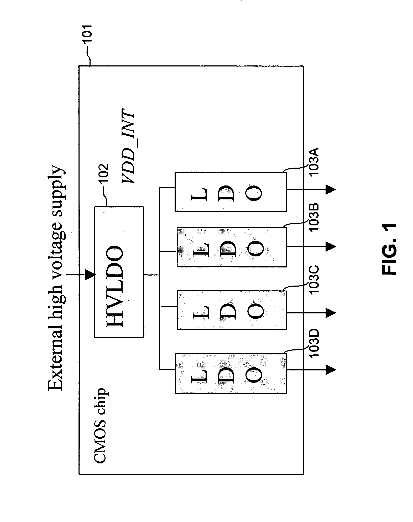
FIG. 1 illustrates a voltage regulator arrangement of the present invention. As shown in FIG. 1, a CMOS voltage regulator chip 101 has an external high voltage supply as an input. The external high voltage supply may be a main battery, typically with a maximum output voltage of about 3.3-4.6 volts, or a line charger input (5-20V). The output voltage range of 3.3-4.6 volts is typical for lithium ion type batteries. The regulator chip 101 includes one high voltage low dropout (HVLDO) regulator 102 (hereafter, sometimes referred to as “high voltage regulator”), outputting a voltage VDD13 INT, which is at or below the breakdown voltage of the downstream CMOS devices.

In series with the high voltage low dropout regulator 102 are a plurality of low voltage low dropout regulators (LVLDO's) 103A-103D (hereafter, sometimes referred to as “low vol...


PUM


Abstract

A voltage regulator includes a first stage capable of receiving a reference voltage and capable of having a first current flowing through the first stage. A second stage is capable of having a second current flowing through the second stage. A third stage is capable of outputting an output voltage and capable of having a third current flowing through the second stage. The first, second and third currents are proportional to each other throughout a range of operation of the voltage regulator between substantially zero output current and maximum output current. The first stage drives the second stage as a low input impedance load.

Description

BACKGROUND OF THE INVENTION 1. Field of the Invention The present invention relates to power management units for portable applications, and more particularly to high efficiency, low loss power management units. 2. Description of the Related Art Power management in portable electronic systems, such as cellular phone, portable PDAs, laptops, etc. is an important issue, as consumers increasingly demand longer times between recharging. For example, a cellular phones typically has three power sources: a rechargeable main battery, a small coin-sized backup battery, and a line charger that can be plugged into a wall outlet or a car outlet. Typical main battery voltage is between about 3.3 volts and 4.6 volts. Typical charger voltage is 5-20V. Power management units (PMUs) are often manufactured using non-standard (i.e., high voltage) CMOS processes or using bi-polar. In the case of CMOS PMUs, power efficiency and the breakdown voltage of the CMOS devices are important parameters to c...

Claims


Application Information

Patent Timeline
Patent Type & Authority Applications(United States)
IPC IPC(8): G05F1/575
CPCG05F1/575G05F1/56
Inventor CHEN, CHUN-YING
Owner AVAGO TECH INT SALES PTE LTD
Why Eureka
Try Eureka