Power line property measurement devices and power line fault location methods, devices and systems

a technology of power line property measurement and power line fault location, which is applied in the direction of fault location by conductor type, measurement using dc-ac conversion, instruments, etc., can solve the problems of dangerous or costly situation, circuit breaker to open, and overhead power line disruption or knockdown, so as to facilitate installation and monitoring, quick and efficient guide power line repair personnel, and enhance the safety of power line workers

Inactive Publication Date: 2005-02-24
UBER ARTHUR E III +1
View PDF4 Cites 174 Cited by
  • Summary
  • Abstract
  • Description
  • Claims
  • Application Information

AI Technical Summary

Benefits of technology

[0017] In several embodiments, the devices, systems, and methods of the present invention can quickly and efficiently guide power line repair personnel to the location of a fault. For example, a device of the present invention, which is in proximity to a power line, can indicate whether or not a surge current has passed through that power line just prior to the power being shut off. The device can also monitor and communicate other characteristics of the power line that would be beneficial to the power line company to know. Likewise, a set of devices of the present invention can be placed in proximity to a power line along the length of the power line to indicate the path taken by a surge current that passed through that section of the line just prior to the power being shut off. Moreover, one or more of the devices of the present invention can communicate with other similar devices or another device to aid in determining the fault location. The devices of the present invention can further provide an indication of whether a power line is currently powered to enhance the safety of power line workers.
[0018] The systems and devices of the present invention are relatively easy for power companies to install and to monitor. The sophistication of the monitoring systems can vary depending upon the power company's needs and willingness to invest in the system. The systems and devices of the present invention are also relatively simple to manufacture, distribute, and install at low costs.

Problems solved by technology

These overhead power lines can be disrupted or knocked down by many things, for example in an ice storm, by a tree falling as a result of wind or lightening, or because of a vehicle hitting a utility pole.
Because our convenience, livelihood, and sometimes even individual's lives are dependent upon electricity, this can lead to a dangerous or costly situation when many people are left without power for a significant length of time.
When a wire breaks and falls to the ground, contacts an uninsulated part of the pole or another wire, or if a transformer, insulator or other piece of equipment fails, the surge of current to ground causes a circuit breaker to open.
But finding the location of the fault between the substation and the buildings can be difficult because of the branching nature of power circuits and the remoteness and difficulty observing some runs of the power line.
This is a very arduous task; all the while leaving customers without power.
It is made more complicated because of the branching nature of residential power distribution system.
However, not every downed tree harmed the power lines, because in some areas the power lines are located in alleys or along the property line between houses, rather than along the streets.
There is currently no way to easily retrofit a fault location device or system to an existing, operating power line.

Method used


Image

  • Power line property measurement devices and power line fault location methods, devices and systems
  • Power line property measurement devices and power line fault location methods, devices and systems
  • Power line property measurement devices and power line fault location methods, devices and systems

Examples


Embodiment Construction

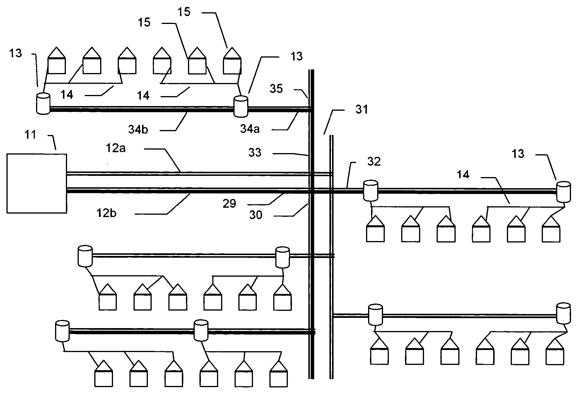
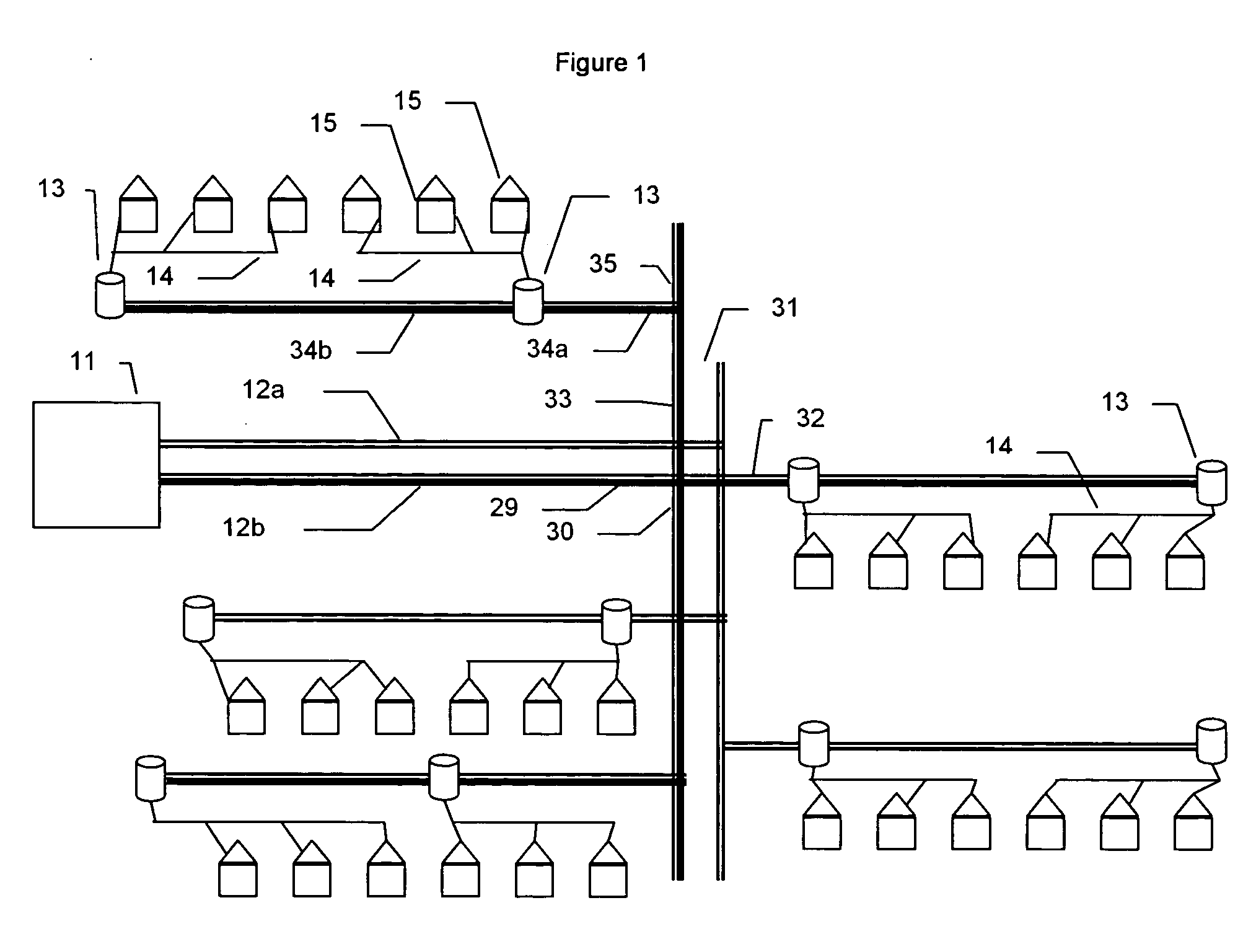
[0028]FIG. 1 is a simple schematic of a local power distribution grid showing how electricity is distributed from a power substation 11 to individual houses 15. The power substation 11 feeds two high voltage lines, 12a and 12b. The number of lines can vary. Three (3) is a common number because of the benefits of 3 phase AC power. The power substation contains circuit breakers that interrupt the flow of power to the high voltage lines 12a and 12b if the current drawn exceeds the capacity of the lines or other equipment. High voltage lines 12a and 12b can be on the order of 13,000 Volts (V) and carry currents of hundreds of amperes. These lines are on the very top of the power poles. They branch as needed and periodically are connected to step down transformers 13. These transformers reduce the voltage to + / −110 V for use in the home. The output of these transformers is usually 3 wires indicated as power line 14, a +110 V, a neutral, and a −110 V which run along the power poles below ...


PUM


Abstract

A device for use in locating a fault on a power line of a power distribution system includes: at least one sensor for measuring at least one property of the power line, and at least one output device in operative connection with the sensor to signal a state of the power line. The signaled state of the power line is determined from the measured property and indicates whether a fault has occurred in the power line. The output device can, for example, signal a current state or a previous state of the power line. The device can further include a controller in operative connection with the output device to control the operation of the output device based upon at least one of the current state or the past state of the power line. A device for use in measuring a property of power line of a power distribution system includes: a connector adapted to place the device in operative connection with the power line in the power distribution system without taking the power line out of operation; a sensor for measuring a property of the power line, and an output device in operative connection with the sensor to transmit a signal representative of the measured property.

Description

[0001] CROSS REFERENCE TO RELATED APPLICATION [0002] This application claims benefit of the priority date of U.S. Provisional Patent Application Ser. No. 60 / 497,108, filed Aug. 22, 2003, the disclosure of which is incorporated herein by reference.FIELD OF THE INVENTION [0003] The present invention relates to measurement devices for measurement of power line properties and to methods, devices and systems for determining the location of power line faults. The methods devices and systems of the present invention can, for example, be used by power distribution companies to aid their crews in more easily and quickly finding power line faults, and, as a result, better serve their customers. BACKGROUND OF THE INVENTION [0004] Electricity is essential in all industrialized countries. It is used to power everything from small household appliances to large factories. To deliver electricity to each individual house, school, hospital or other building, a complex branching system or network of p...

Claims


Application Information

Patent Timeline
Patent Type & Authority Applications(United States)
IPC IPC(8): G01R15/14G01R31/08
CPCG01R15/142Y04S10/522G01R31/086Y04S10/52
Inventor UBER, ARTHUR E. IIIUBER, BRONWYN E.
Owner UBER ARTHUR E III
Why Eureka
Try Eureka