Liquid crystal display device

a liquid crystal display and display device technology, applied in non-linear optics, instruments, optics, etc., can solve the problems of difficult to obtain a uniform multi-domain orientation, large “viewing angle dependency” and varying the appearance of the displayed image, and achieve the highest transmittance, maximum light efficiency, and increased light efficiency

Inactive Publication Date: 2005-02-24
SHARP KK
View PDF10 Cites 33 Cited by
  • Summary
  • Abstract
  • Description
  • Claims
  • Application Information

AI Technical Summary

Benefits of technology

[0012] In view of the above-mentioned conventional problems, the present invention has been devised for the purpose of realizing a liquid crystal display device with a desirable viewing angle characteristic which has a sufficiently stable orientation and a sufficiently high response speed and yet can be produced efficiently.

Problems solved by technology

However, a problem of a liquid crystal display device is that the appearance of the displayed image varies depending upon the direction from which it is viewed, i.e., the “viewing angle dependency” is substantial.
However, a study conducted by the inventor of the present invention revealed that the techniques disclosed in the publications above have the following problems.
With the method of Japanese Laid-Open Patent Publication No. 6-301036, it is difficult to obtain a uniform multi-domain orientation.
Moreover, when the value of the voltage applied across the liquid crystal layer is changed, it takes a relatively long time to complete the change in the orientation according to the change in the voltage value; that is, the response speed is slow.
It is believed that these problems are caused by the fact that the orientation-regulating force for achieving a multi-domain orientation (a force for orienting the liquid crystal molecules in a particular direction) is relatively weak in this method.
However, this method has the following problems.
First, if the method disclosed in this publication is employed, it is necessary to provide a protrusion, a depression or a slit on both of the pair of substrates interposing the liquid crystal layer therebetween in order to achieve a multi-domain orientation, thereby complicating the production process of the liquid crystal display device and lowering the production efficiency.
Therefore, it is difficult to provide a protrusion or a depression on the surface of the plasma cell substrate which is closer to the liquid crystal layer.
Moreover, although the thin glass plate itself functions as an electrode (it is sometimes called a “virtual electrode”), it is not an electrode made of a conductive layer, whereby a slit (an opening provided in an electrode) cannot be provided therein.
Therefore, it is very difficult to use the method disclosed in this publication with PALCs.
However, since the positional precision of the orientation regions depends directly upon the precision of the attachment of the substrates with each other, the orientation region cannot be miniaturized excessively.

Method used


Image

  • Liquid crystal display device
  • Liquid crystal display device
  • Liquid crystal display device

Examples


embodiment 1

[0112] A liquid crystal display device of Embodiment 1 is an active matrix type liquid crystal display device using TFTs, wherein picture element electrodes arranged in a matrix having rows and columns function as the first electrode, and a counter electrode which is used commonly to the plurality of picture element electrodes functions as the second electrode.

[0113]FIG. 3A and FIG. 3B schematically illustrate a liquid crystal display device 300 according to Embodiment 1 of the present invention. FIG. 3A is a plan view schematically illustrating a single picture element region (a TFT element, a storage capacitor element, etc., are omitted), and FIG. 3B is a cross-sectional view taken along line 3B-3B′ of FIG. 3A.

[0114] The liquid crystal display device 300 includes a TFT substrate 300a, a counter substrate 300b and a liquid crystal layer 330 provided between the TFT substrate 300a and the counter substrate 300b. The liquid crystal layer 330 is a vertical alignment type liquid crys...

embodiment 2

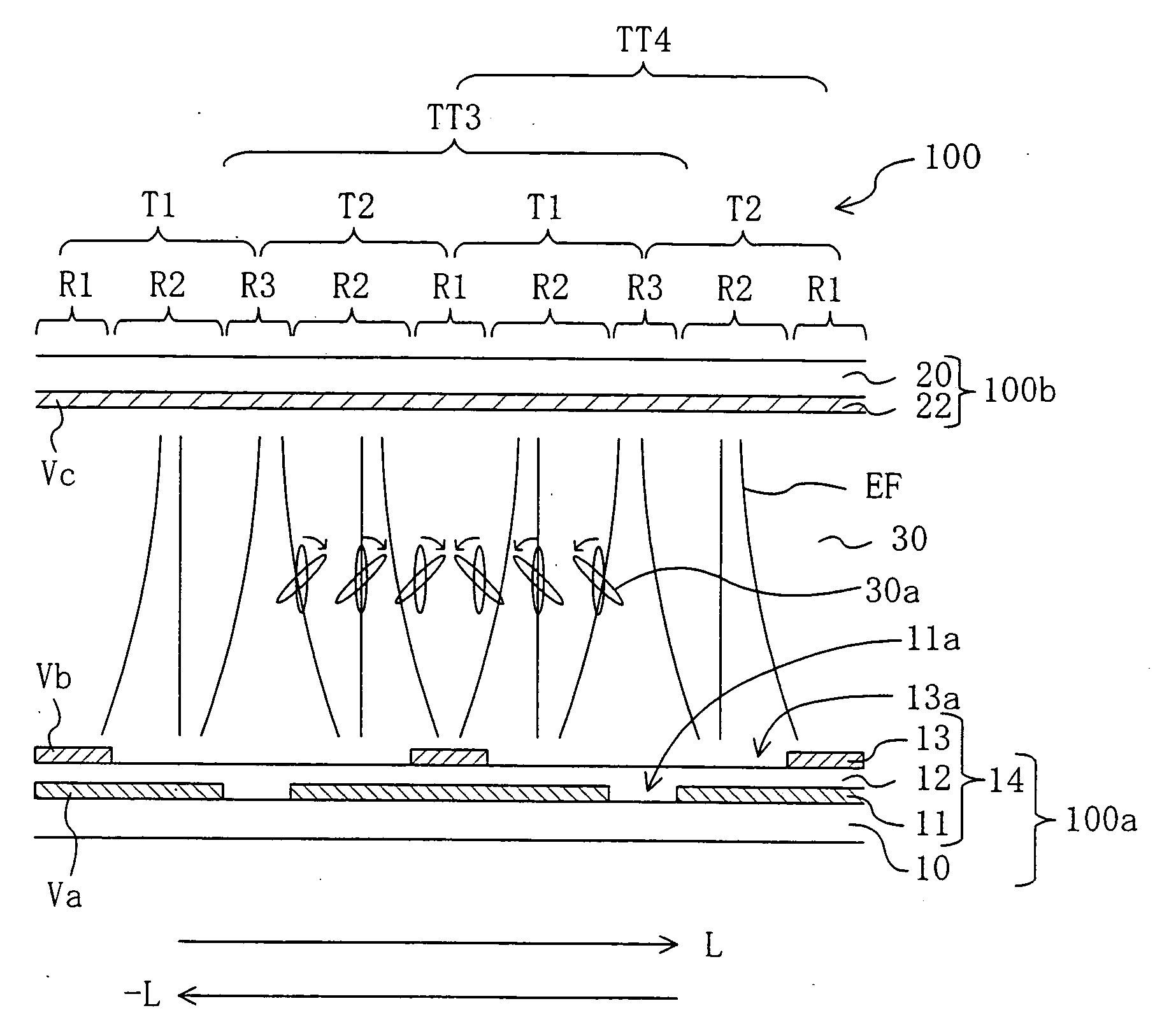
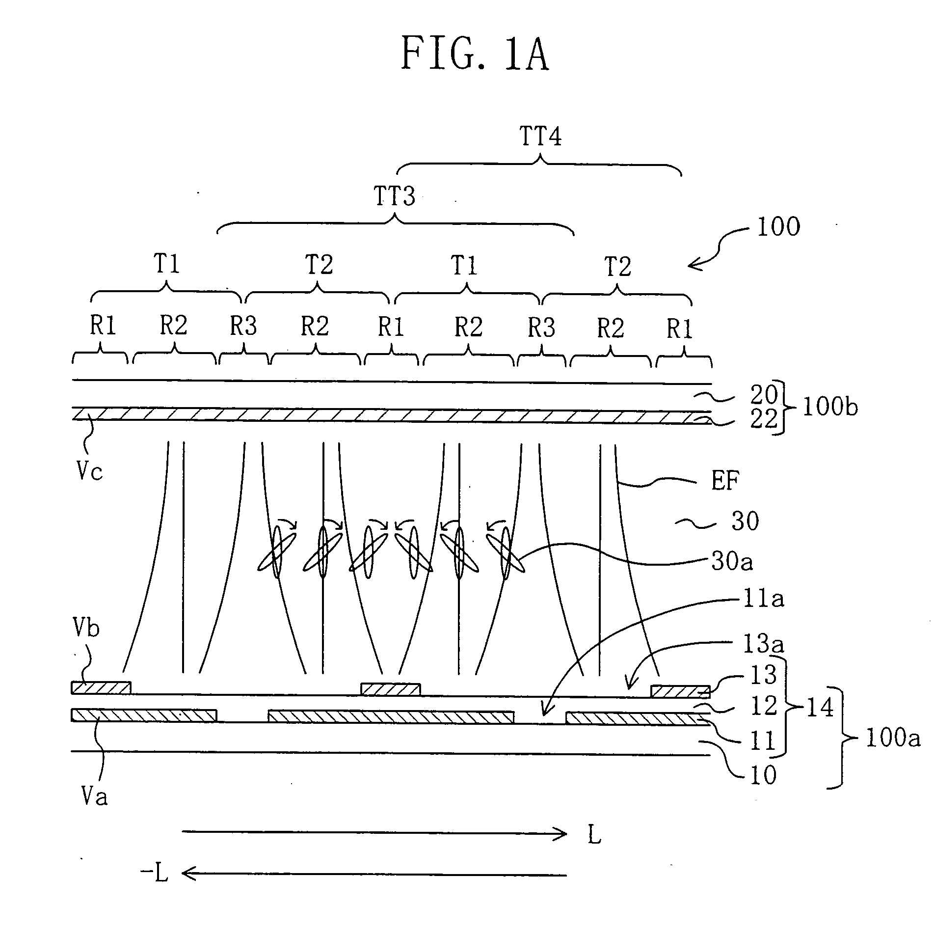
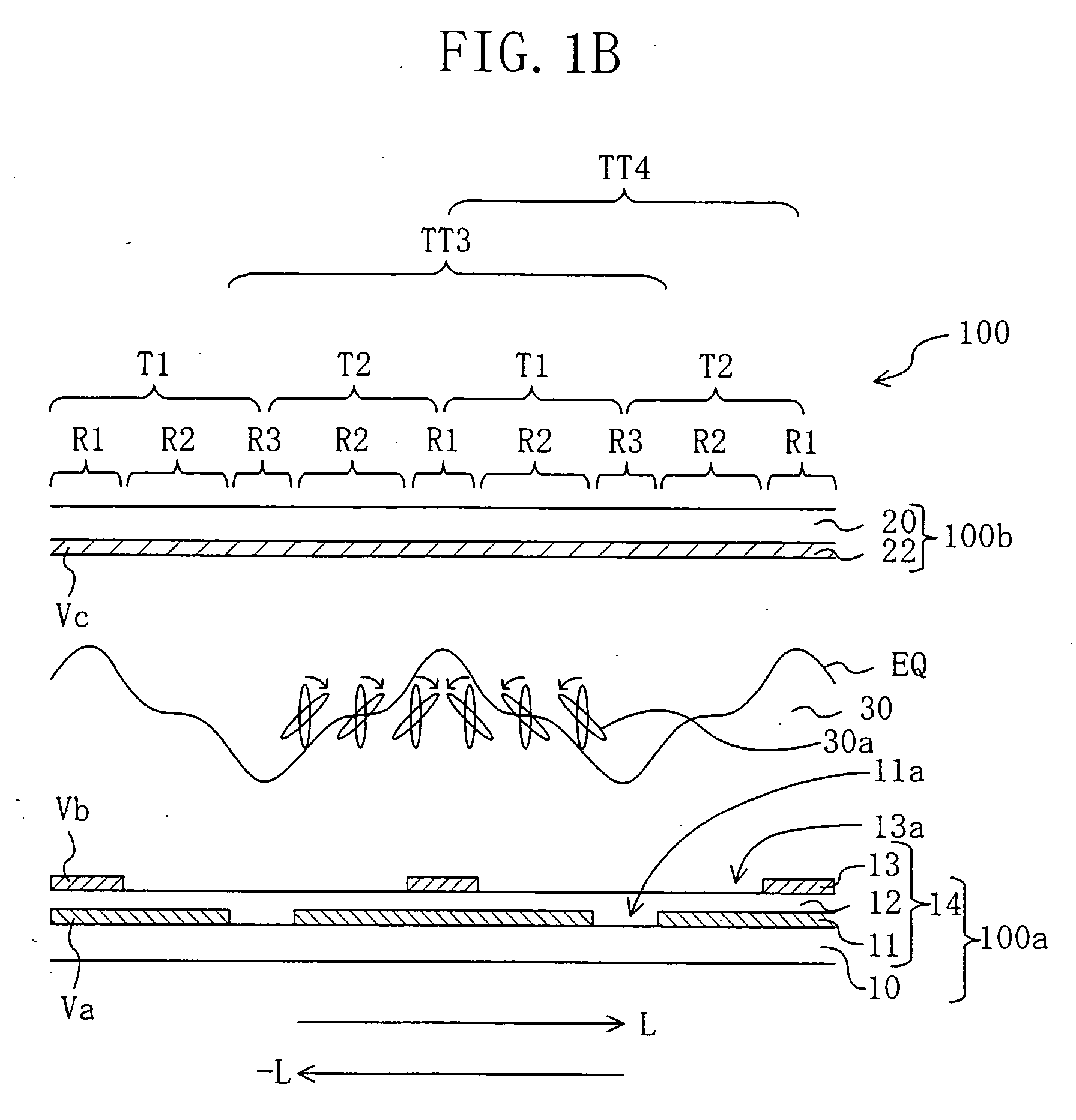
[0138] The TFT type liquid crystal display device 300 of Embodiment 1 employs the structure of the first electrode 14 illustrated in FIG. 1A for the picture element electrodes of the conventional TFT type liquid crystal display device. In contrast, a TFT type liquid crystal display device of Embodiment 2 employs a structure similar to that of the first electrode 14 illustrated in FIG. 1A for a counter electrode of the conventional TFT type liquid crystal display device. The structure of the liquid crystal display device of Embodiment 2 may be the same as that of the conventional liquid crystal display device (having the structure of the liquid crystal display device 300 of Embodiment 1 except for the picture element electrode 314) except for the structure of the counter electrode. Accordingly, only the structure of the counter electrode will be described below.

[0139]FIG. 8 shows a plan view of a counter substrate 600b of the liquid crystal display device of Embodiment 2. The counte...

embodiment 3

[0144] According to the present invention, it is possible to obtain a sufficient orientation-regulating force by, for example, employing an electrode structure similar to that of the first electrode 14 illustrated in FIG. 1A for the structure of one of a pair of electrodes which oppose each other via a liquid crystal layer therebetween. Therefore, even with a PALC, for which it is difficult to obtain an orientation-regulating force with the conventional structure (e.g., that disclosed in Japanese Laid-Open Patent Publication No. 11-258606), a sufficient orientation-regulating force can be obtained by employing the electrode structure of the present invention.

[0145] The structure and operation of a liquid crystal display device 700 of Embodiment 3, which uses the present invention with a PALC, will now be described.

[0146]FIG. 9 schematically illustrates the liquid crystal display device 700 of Embodiment 3. The liquid crystal display device 700 includes a liquid crystal display cel...


PUM

PropertyMeasurementUnit
areaaaaaaaaaaa
thicknessaaaaaaaaaa
angleaaaaaaaaaa

Abstract

A first electrode 14 provided in a liquid crystal display device of a vertical alignment mode includes, for each picture element region, a lower conductive layer 11, a dielectric layer 12 covering the lower conductive layer 11, and an upper conductive layer 13 provided on one side of the dielectric layer 12 which is closer to a liquid crystal layer 30. The upper conductive layer 13 includes an upper layer opening 13a, and the lower conductive layer 11 includes a lower layer opening 11a, thus forming first, second and third regions (R1, R2, R3) having gradually decreasing electric field strengths. Liquid crystal molecules 30a of the liquid crystal layer 30 in an orientation-regulating region T1 in which the first, second and third regions are arranged in this order in a predetermined direction change the orientation direction thereof so that they are inclined in a single direction in the presence of an applied voltage.

Description

BACKGROUND OF THE INVENTION [0001] The present invention relates to a liquid crystal display device. More specifically, the present invention relates to a liquid crystal display device having a wide viewing angle characteristic. [0002] A liquid crystal display device is a flat display device with advantageous features such as a reduced thickness, a reduced weight, a reduced power consumption, etc. However, a problem of a liquid crystal display device is that the appearance of the displayed image varies depending upon the direction from which it is viewed, i.e., the “viewing angle dependency” is substantial. The substantial viewing angle dependency of a liquid crystal display device is primarily due to the fact that liquid crystal molecules having a uniaxial optical anisotropy are uniformly oriented in the display plane. [0003] An effective method to improve the viewing angle characteristic of a liquid crystal display device is to produce a so-called “multi-domain orientation” by for...

Claims


Application Information

Patent Timeline
Patent Type & Authority Applications(United States)
IPC IPC(8): G02F1/1333G02F1/1337G02F1/1343G02F1/139
CPCG02F1/133707G02F2201/128G02F1/1393G02F1/134336G02F1/1337
Inventor SHIMOSHIKIRYO, FUMIKAZU
Owner SHARP KK
Why Eureka
Try Eureka