Variable bandwidth code-tracking loop with improved signal dynamics loop noise and sensitivity

a code-tracking loop and variable bandwidth technology, applied in the field of filters, can solve the problems of loss of the ability to track high dynamics, limitation of allowing the transition from an initial bandwidth loop to a lower bandwidth loop only once, and achieve the effect of controlling the bandwidth of the dynamic code-tracking loop and improving the trade-off between processor memory and power requirements

Inactive Publication Date: 2005-02-24
CSR TECH INC
View PDF12 Cites 22 Cited by
  • Summary
  • Abstract
  • Description
  • Claims
  • Application Information

AI Technical Summary

Benefits of technology

The present invention describes a dynamic tracking loop filter that overcomes the limitation of the prior art. The dynamic tracking loop filter is a variable bandwidth code-tracking loop. The variable bandwidth code-tracking loop is able...

Problems solved by technology

Previous approaches have improved noise performance and sensitivity by using lower bandwidth tracking loops that result in the loss of the ability to track high dynamics in addition to the “pull in” capabilities being lost.
But, such designs have the limitation of all...

Method used


Image

  • Variable bandwidth code-tracking loop with improved signal dynamics loop noise and sensitivity
  • Variable bandwidth code-tracking loop with improved signal dynamics loop noise and sensitivity
  • Variable bandwidth code-tracking loop with improved signal dynamics loop noise and sensitivity

Examples


Embodiment Construction

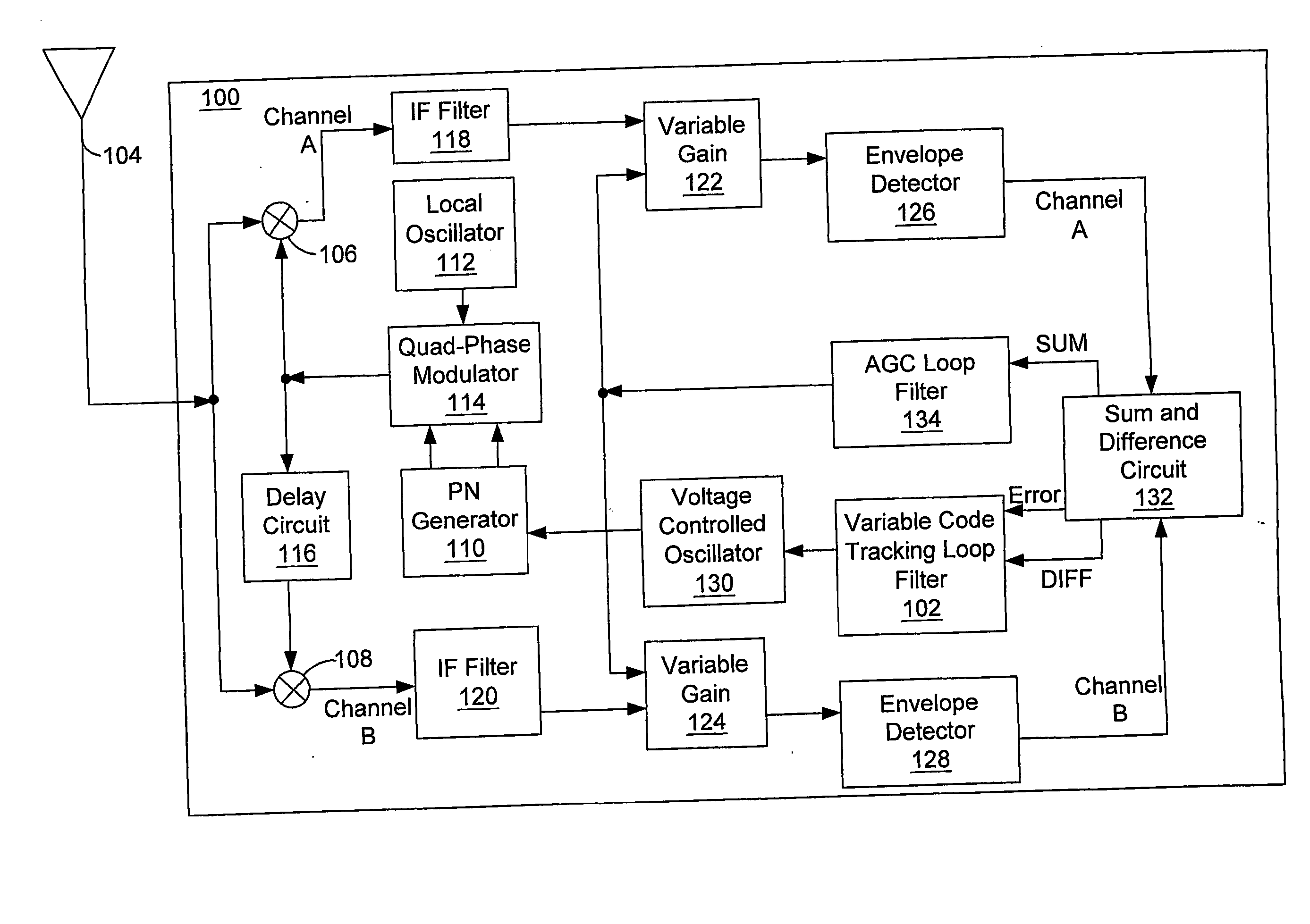
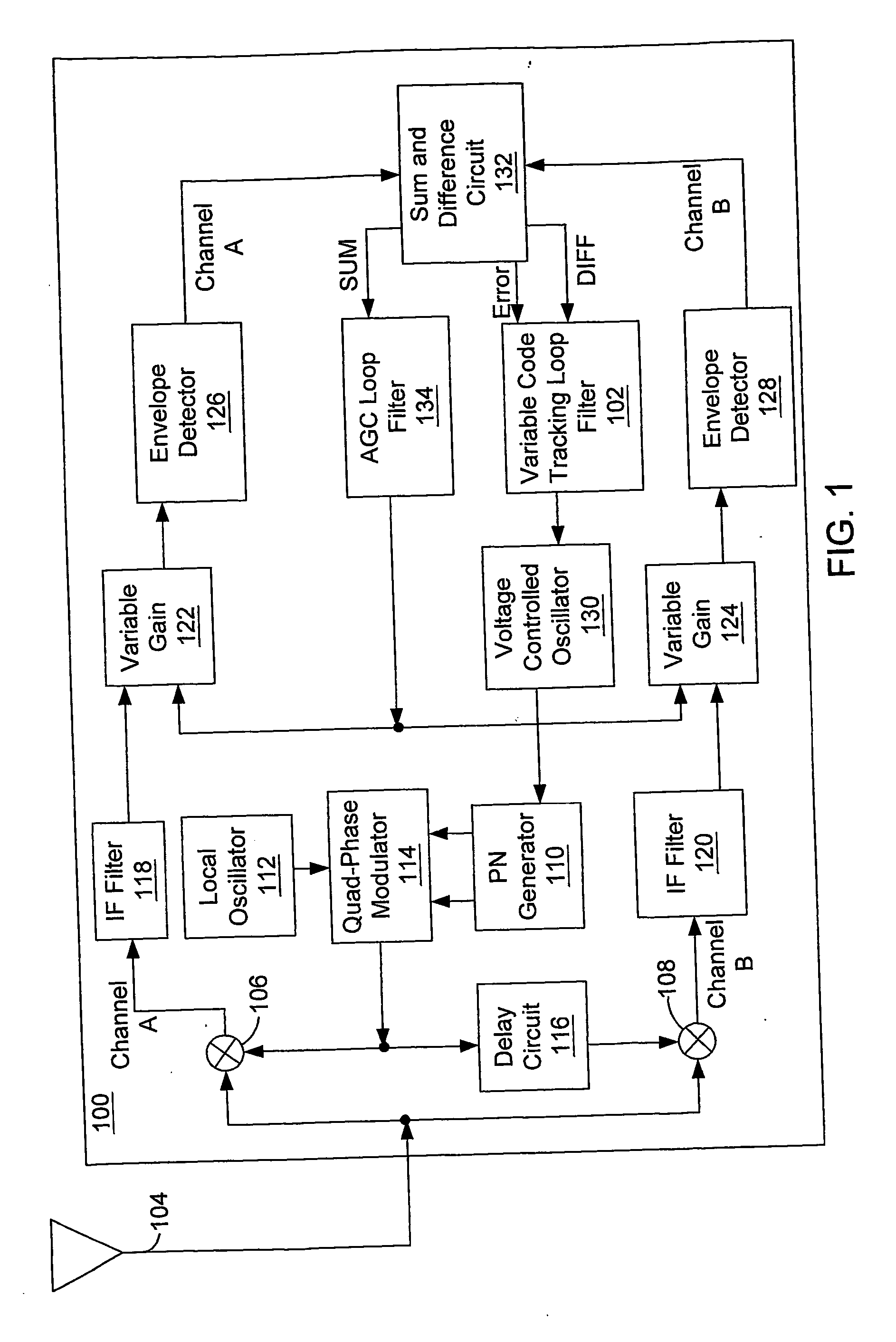
In FIG. 1, a block diagram of timing control circuit in a GPS receiver 100 having a Variable Code-Tracking Loop Filter 102 is shown. An incoming spread spectrum IF signal containing the transmitted pseudo-noise (PN) code with which the locally generated PN code is to be synchronized is distributed from an Antenna 104 to a pair of Mixers 106 and 108. In each of the Mixers 106 and 108, the incoming spread spectrum IF signal is combined with a PN signal code locally produced by PN Code Generator 110, Local Oscillator 112 and Quad-phase Modulator 114. To provide a relative phase offset between the codes applied to mixers 106 and 108, a delay circuit 116 is inserted in the signal path between the output of the Quad-phase Modulator 114. The output Mixers 106 and 108 are filtered by IF Filters 118 and 120 and applied via a pair of Variable Gain Amplifiers 122 and 124 to Envelope Detectors 126 and 128 respectively. The outputs of Envelope Detectors 126 and 128 represent the degree of corre...


PUM


Abstract

A variable code-tracking loop filter in a receiver having the ability to change its parameters multiple times in response to received signals.

Description

BACKGROUND OF THE INVENTION 1. Field of the Invention This invention relates generally to filters in connection with a wireless communication device and more practically to code-tracking loops. 2. Related Art A Satellite Positioning System (SPS) receiver such as a Global Positioning System (GPS) receiver converts a received spread spectrum IF signal to a signal of a lower frequency. This lower frequency signal is obtained by mixing the received signal with a pure sinusoidal signal generated by a local oscillator. The frequency of the sinusoidal signal is the difference between the original (Doppler-shifted) received carrier frequency and the local oscillator signal. The lower frequency signal is then processed by signal tracking circuits in the GPS device. A common class of signal processing techniques that is used to track carrier phase includes “code-correlating” approaches. Code-correlating receivers use tracking loops or tracking loop filters to extract the necessary measur...

Claims


Application Information

Patent Timeline
IPC IPC(8): G01S1/00H03L7/093H03L7/107H04B1/707
CPCG01S19/29G01S19/30H03L7/093H04B2201/70715H03L7/1075H04B1/7085H03L7/107
Inventor CHANSARKAR, MANGESH
Owner CSR TECH INC
Why Eureka
Try Eureka