Method of altering the frequency of blades for thermal fluid-flow machines

Inactive Publication Date: 2005-02-24
ALSTOM TECH LTD
View PDF9 Cites 13 Cited by
  • Summary
  • Abstract
  • Description
  • Claims
  • Application Information

AI Technical Summary

Benefits of technology

[0017] In addition, smooth continuous transitions can be achieved in the deposit thickness, in the course of which the deposit material

Problems solved by technology

In the process, there are always parameters which, due to assumptions, only inadequatel

Method used


Image

  • Method of altering the frequency of blades for thermal fluid-flow machines
  • Method of altering the frequency of blades for thermal fluid-flow machines

Examples


Example

[0021] The invention is explained in more detail below with reference to an exemplary embodiment and FIGS. 1 and 2.

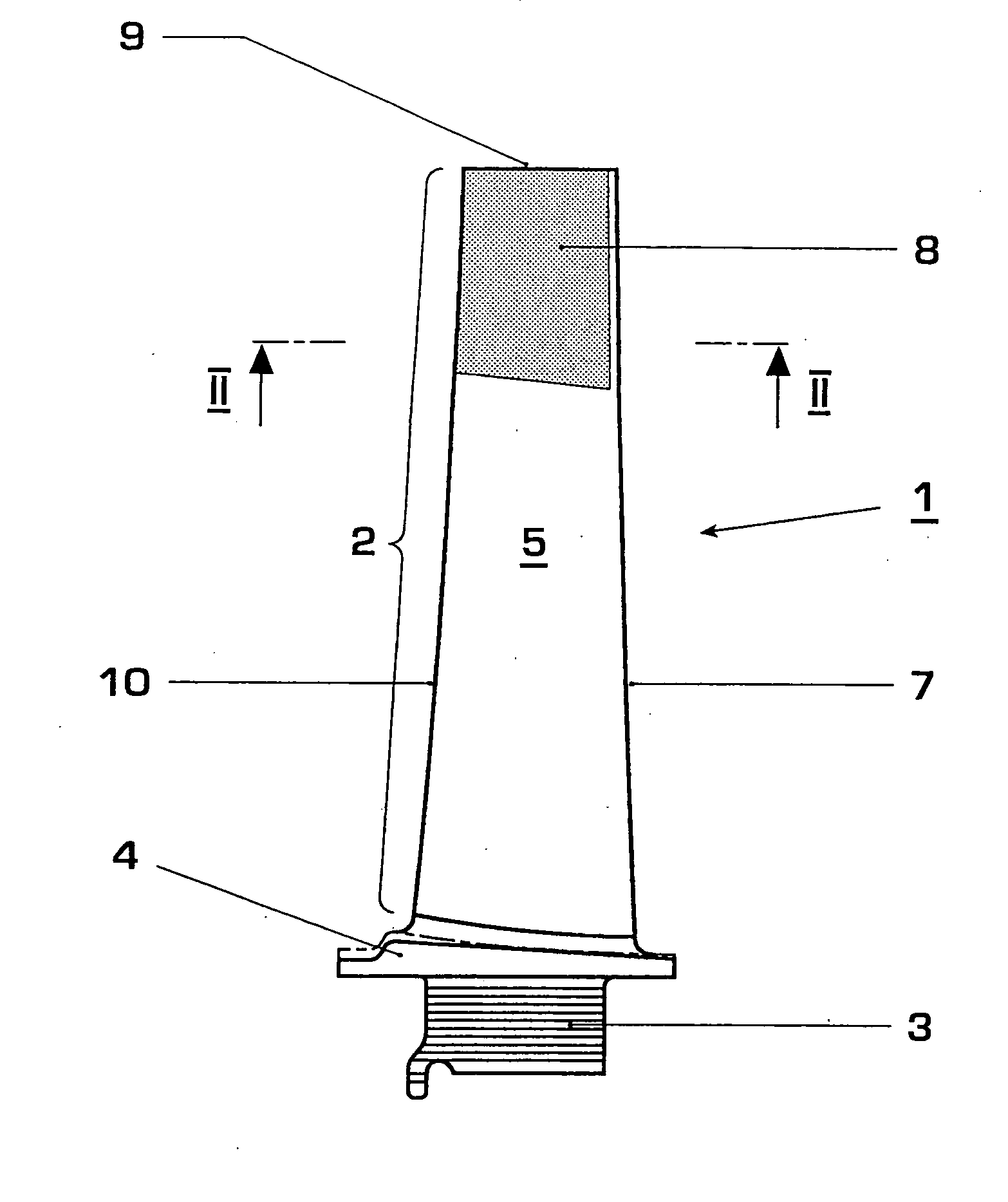
[0022]FIG. 1 shows a moving blade 1 of a gas turbine in side view. The moving blade 1 consists of an airfoil 2, a blade root 3 and a platform 4 which is arranged in between and from which the airfoil 2 extends in an integral manner. The blade root 3 serves to fasten the turbine blade1 in a turbine rotor (not shown). The airfoil 2 has a pressure side 5 and a suction side 6 (not visible in FIG. 1), which adjoin one another at a trailing edge 7, and a blade tip 9. The view of the pressure side 5 of the airfoil 2 is shown in FIG. 1.

[0023]FIG. 2 shows a section along the plane II-II of FIG. 1. For reasons of simplification, the inner contour of the blade 1, which has an internal cooling system, is not shown in FIG. 2.

[0024] In order to remove frequency differences between the frequency theoretically calculated during the design phase and the frequency actually measured on...


PUM

PropertyMeasurementUnit
Metallic bondaaaaaaaaaa
Frequencyaaaaaaaaaa

Abstract

A method of altering the frequency of blades (1) having an airfoil (2) with a suction side (6), a pressure side (5), a leading edge (10), a trailing edge (7) and a blade tip (9), and including a blade root (3), in particular turbine blades, for thermal fluid-flow machines. A metallic coating (8) formed of a material identical to the parent material is applied to the blade (1), already ready for use, in the region of the blade tip (9), the thickness of the coating (8) tapering continuously at the trailing edge (7) and in the radial direction toward the blade root (3).

Description

[0001] This application is a Continuation of, and claims priority under 35 U.S.C. § 120 to, International application number PCT / CH03 / 00022, filed Jan. 16, 2003, and claims priority under 35 U.S.C. § 119 to Swiss application number 2002 0104 / 02, filed Jan. 22, 2002, the entireties of both of which are incorporated by reference herein.BACKGROUND OF THE INVENTION [0002] 1. Field of the Invention [0003] The invention relates to the field of thermal fluid-flow machines. It relates to a method of altering the frequency of blades, in particular turbine blades, which are already largely ready for use for fitting in the fluid-flow machine. [0004] 2. Brief Description of the Related Art [0005] The output of a gas turbine is essentially determined by the processed mass flows such as fuel and air. [0006] In addition to the seals, bearings, etc., in particular the quality of the blading has an effect on the efficiency level of a gas turbine. The blade dimensions, e.g. the chord length, the blad...

Claims


Application Information

Patent Timeline
IPC IPC(8): C23C4/00F01D5/16
CPCC23C4/00F05D2230/311F05D2230/90F01D5/16
Inventor BENEDETTI, BRUNOKIENINGER, ANDREASNAGLER, CHRISTOPHSTENGELE, JOERG
Owner ALSTOM TECH LTD
Why Eureka
Try Eureka