Method and apparatus for diagnosing a cyclic system

a cyclic system and cyclic system technology, applied in the direction of instruments, electrical digital data processing, hardware monitoring, etc., can solve the problems of frequent maintenance and trouble shooting, waste of time and relatively expensive procedures, and high cost, and achieve the effect of diagnosing the operational status of the fluid power system

Active Publication Date: 2005-02-24
FESTO AG & CO KG
View PDF38 Cites 62 Cited by
  • Summary
  • Abstract
  • Description
  • Claims
  • Application Information

AI Technical Summary

Benefits of technology

It is an advantage of the present invention to provide a method and apparatus for diagnosing a cyclic system.
to provide a method and apparatus for diagnosing a cyclic system.
It is another advantage of the present invention to provide a method for diagnosing the operational status of a fluid power system using one system characteristic.
In the efficient attainment of these and other advantages the present invention provides a method and apparatus for determining the service life of a cyclic system. The method includes the steps of determining at least one characteristic of the system to determine a characteristic value and determining a cycle time of the system. The at least one characteristic value is applied to an algorithm in which the characteristic value is integrated to determine a diagnostic value, and comparing the diagnostic value to a predetermined value to determine the operational status of the system.
The apparatus includes a sensor for determining a system characteristic and a calculating unit operatively connected to the sensor. The calculating unit includes circuitry for performing a mathematical integration on the system characteristic to determine a diagnostic value and compares the diagnostic valve to a predetermined value to determine the performance status of the system. A notification device is operatively connected to the calculating unit for indicating the operational status of the system.
In a preferred form of the invention, the characteristic value is flow rate Q and the algorithm to determine the status of the system is K=∫0T⁢Q⁢ⅆt

Problems solved by technology

In order to achieve consistent output and continuity in the various systems, frequent maintenance and trouble shooting is often required.
Such maintenance, however, often requires untimely interruptions of the production process leading to costly down time.
However, since preventative maintenance often requires replacement of components before they actually fail, it must be determined which part is in need of replacement or repair and when.
Accordingly, this method of preventative maintenance can lead to the replacement of parts, which are in fine working order creating a wasteful and relatively expensive procedure.
This method, however, requires significant memory space in order to store the many data points in the cycle.
In addition, high computational speed is needed for comparing the data at each point in the cycle with the predetermined range of data values.
In addition, the use of individual system characteristics has heretofore proven to be unacceptable for providing a reliable picture of system performance for determining periodic maintenance schedules.
While pressure measurements may provide diagnostic information with regard to cylinder function, it does not provide sufficient diagnostic data for valve functions.
The information about cylinder functions would be limited for a time depending function, thus not permitting to differentiate between cylinder failures and other possible failures, e.g., malfunction of valve, clogged silencer, etc.
The flow measurement improves the diagnosis for pneumatic circuit, but still does not provide sufficient diagnosis data for all functions.
However, this cycle time does not provide sufficient diagnostic data to determine whether a particular component is nearing failure.

Method used


Image

  • Method and apparatus for diagnosing a cyclic system
  • Method and apparatus for diagnosing a cyclic system
  • Method and apparatus for diagnosing a cyclic system

Examples


Embodiment Construction

The present invention provides a method and apparatus for providing diagnostic information for determining the operational or performance status of a system for preventative maintenance purposes. The present invention permits the prediction of failures in a fluid power circuit including determination of possibly failing components and failure causes. A prediction of the life cycle of the system or its components under the conditions of a particular application may also be obtained. The present invention uses a minimum number of sensors in the system in order to provide the necessary information.

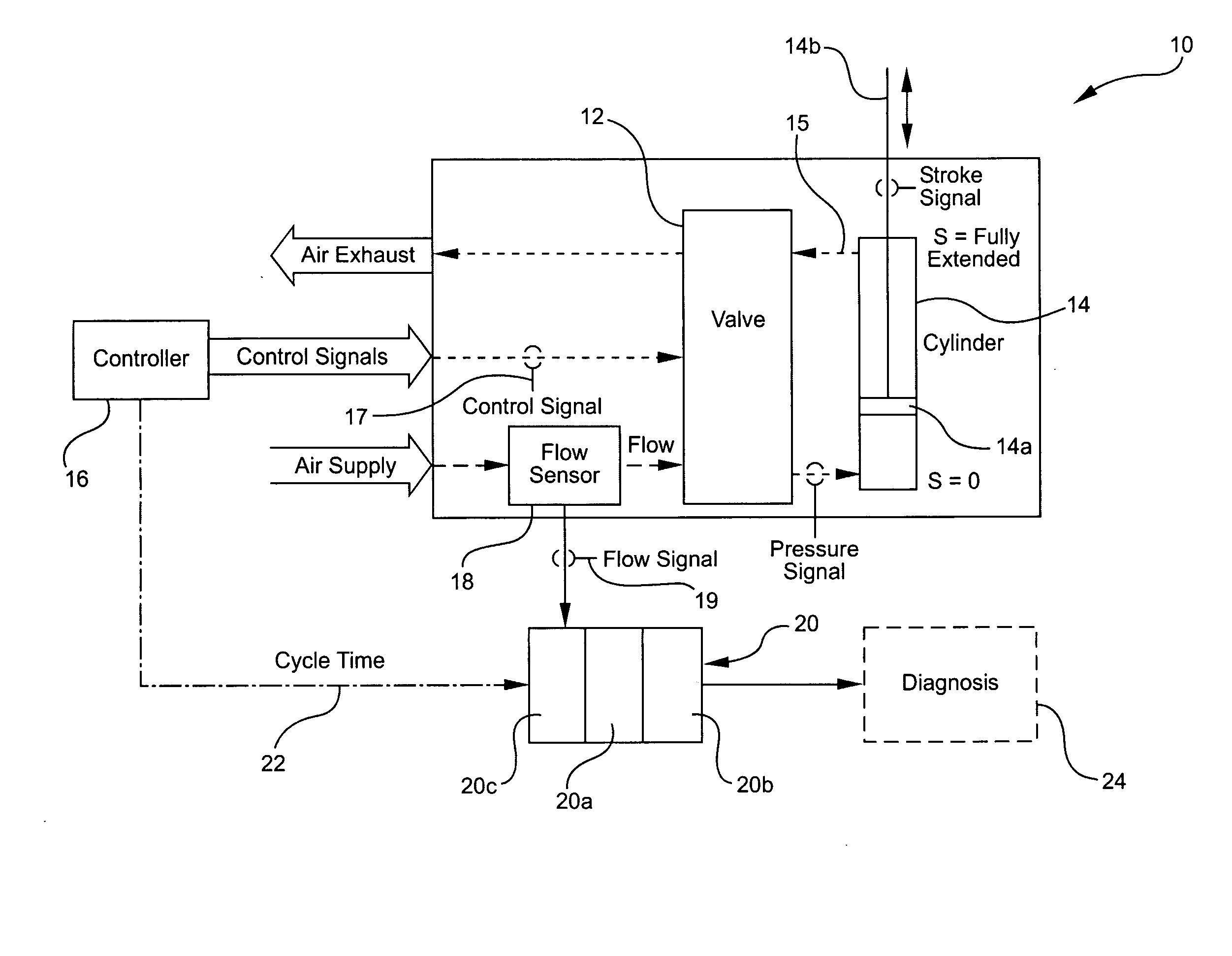
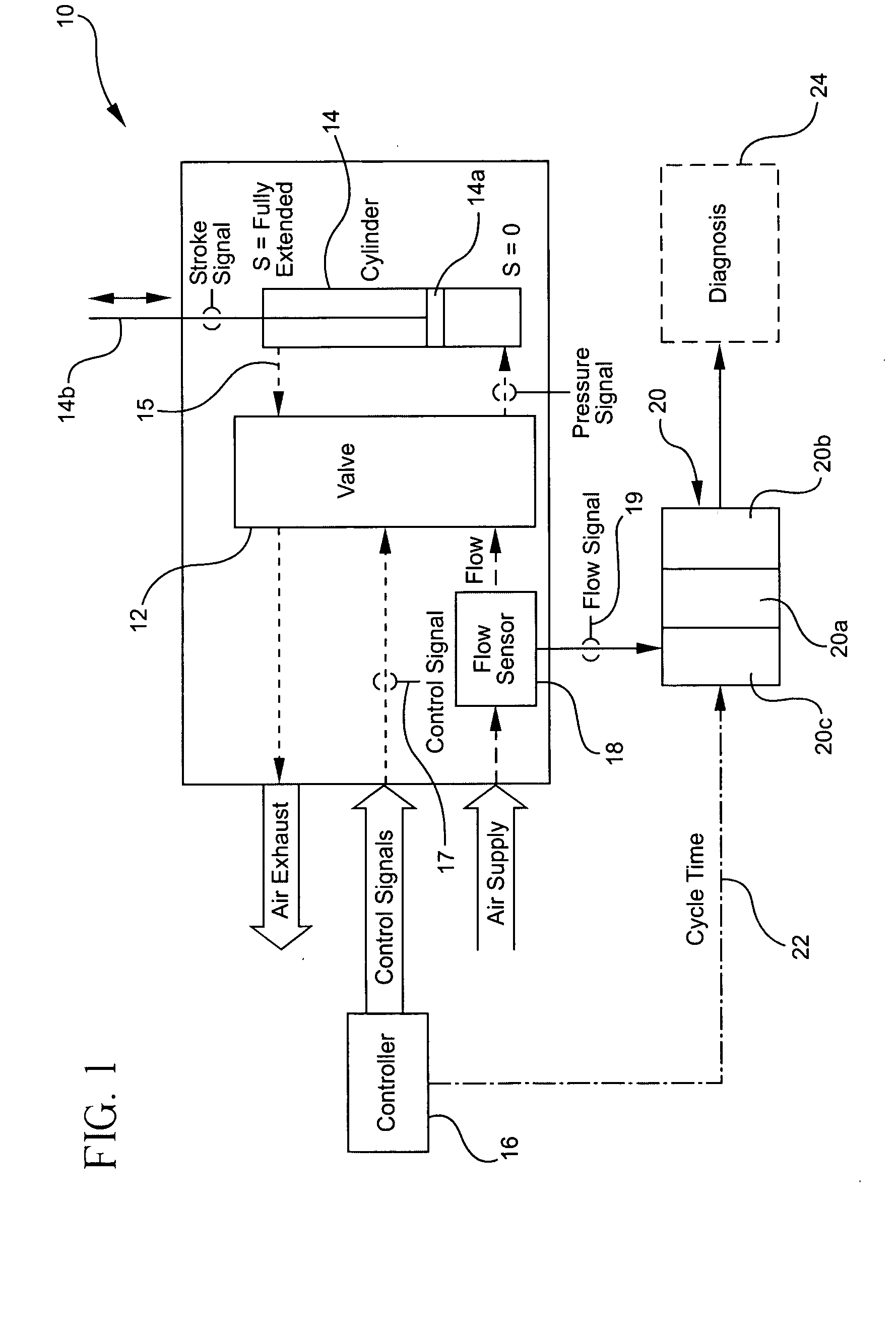
Referring to FIG. 1, a fluid power system, such as pneumatic system 10, generally includes a valve 12, which is operatively connected to an actuator 14. Actuator 14 may include a drive component 14a such as a piston which is attached to a piston rod 14b. The valve 12 receives a signal from a controller 16, which causes the valve 12 to shift at the predetermined time when movement of the ac...


PUM


Abstract

A method and apparatus for determining the service life of a cyclic system the method including the steps of determining at least one characteristic of the system to determine a characteristic value and determining a cycle time of the system. The at least characteristic value is applied to an algorithm in which the characterisitic value is integrated to determine a diagnostic value, and comparing the diagnostic value to a predetermined value to determine the performance status of the system. The apparatus including a sensor for determining a system characteristic and a calculating unit operatively connected to the sensor. The calculating unit including circuitry for performing a mathematical integration on the system characteristic to determine a diagnostic value and comparing the diagnostic valve to a predetermined value to determine the performance status of the system. A notification device operatively connected to the calculating unit for indicating the operational status of the system.

Description

FIELD OF INVENTION The present invention relates to a method and apparatus for diagnosing a cyclic system and more specifically for diagnosing the operational status of a fluid power system. BACKGROUND OF THE INVENTION In the manufacturing environment, various systems are employed in order to operate machinery and transport goods. In order to achieve consistent output and continuity in the various systems, frequent maintenance and trouble shooting is often required. One manor of maintaining machinery is to wait until a failure has occurred in a particular component and then replace that component on an as-needed basis. Such maintenance, however, often requires untimely interruptions of the production process leading to costly down time. Accordingly, there has been a growing trend in machinery maintenance to employ preventative maintenance procedures so that a machine is not brought down by an untimely failure. Instead, maintenance may be performed during planned down times with v...

Claims


Application Information

Patent Timeline
Patent Type & Authority Applications(United States)
IPC IPC(8): F15B19/00F16K37/00G05B23/02G05D7/06
CPCF16K37/0091F15B19/005
Inventor FORSTER, KARL-HEINZBINDER, JOSEF
Owner FESTO AG & CO KG
Why Eureka
Try Eureka