Guide element assembly for a spinning preparation machine

Inactive Publication Date: 2005-03-03
TRUETZSCHLER GMBH & CO KG
View PDF4 Cites 0 Cited by
  • Summary
  • Abstract
  • Description
  • Claims
  • Application Information

AI Technical Summary

Benefits of technology

[0011] The apparatus according to the invention allows simple manufacture, especially of the straight inner wall surface of the recess. It is economical to produce. It is, moreover, simple to handle (assemble)—position correctly and tighten the clamping device, for example, screw. The setting of the guide element thereby obtained does not move again once the clamping device has been tightened. The guide element is advantageous in terms of flow (no undesirable piecings). The apparatus according to the invention is also especially suitable for settings that are established during assembly and do not constantly need to be changed in use. The air flow conditions are adjustable. The setting can be modified in line with various roller diameters.
[0012] In certain embodiments the recess may have, in cross-section, a prismatic shape. Advantageously, the end region and the inner wall surfaces together have a clamping point or clamping line. Advantageously, a non-positive connection is brought about between the guide element and the mounting. Advantageously, a fastening element, for example, a fixing screw, is associated with the guide element at its end (mounting) region. Where the fastening element is a screw, at the end region there is advantageously provided a hole having an internal thread, which co-operates with the fixing screw. Advantageously, the fixing screw passes through a through-hole in the mounting housing. Advantageously, the fixing screw bears against the mounting housing. Advantageously, between the fixing screw and the wall surfaces of the hole there is provided a spacing, which allows the fixing screw to be variously positioned in a lateral direction. Advantageously, between the head of the fixing screw and the mounting housing there is provided a washer, for example, split washer or the like. Advantageously, the washer, for example, a split washer or the like, is curved. Advantageously, the clamping force is produced or introduced by the fixing screw. Advantageously, the clamping force brings about fixing of the end region in a radial direction. Advantageously, without the clamping force, pivoting of the guide element, guide vane or the like is possible.

Problems solved by technology

The curved inner walls are laborious to produce from a manufacturing point of view.

Method used


Image

  • Guide element assembly for a spinning preparation machine
  • Guide element assembly for a spinning preparation machine
  • Guide element assembly for a spinning preparation machine

Examples


Embodiment Construction

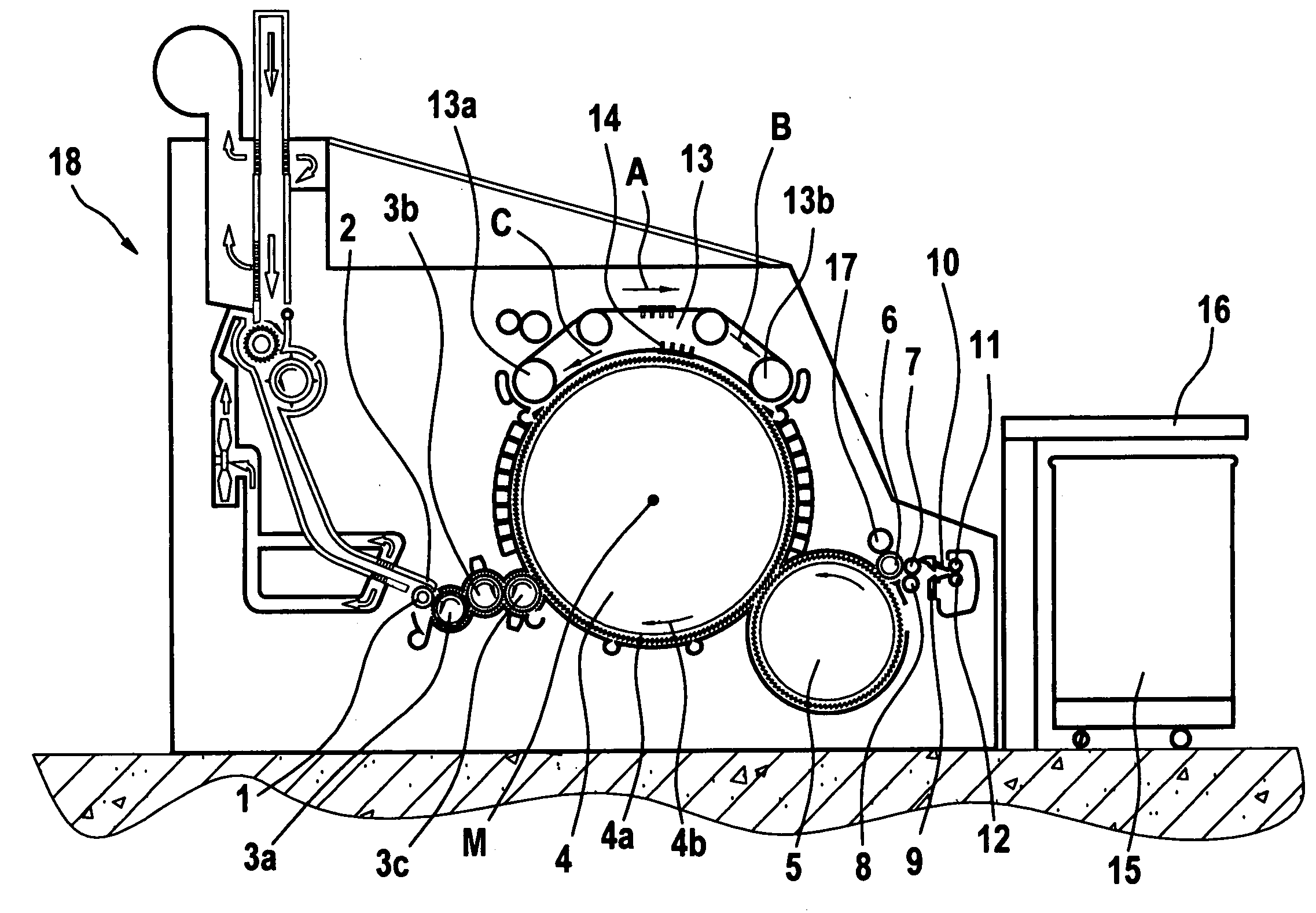
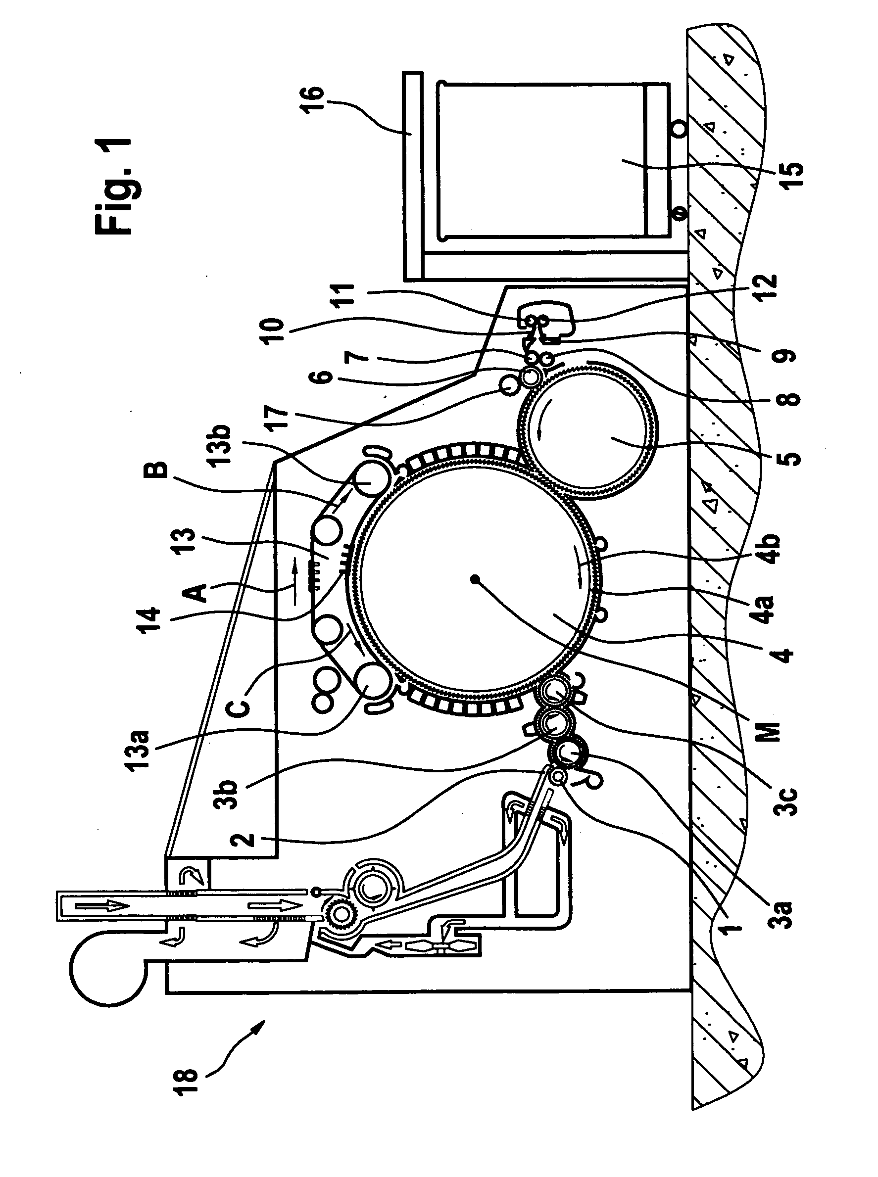
[0018] With reference to FIG. 1, a carding machine, for example a TC 03 (Trade Mark) carding machine made by Trützschler GmbH & Co. KG of Mönchengladbach, Germany, has a feed roller 1, feed table 2, lickers-in 3a, 3b, 3c, cylinder 4, doffer 5, stripper roller 6, nip rollers 7, 8, web-guiding element 9, web funnel 10, draw-off rollers 11, 12, revolving card top 13 having card-top-deflecting rollers 13a, 13b and card top bars 14, can 15 and can coiler 16. Curved arrows denote the directions of rotation of the rollers. Reference letter M denotes the centre (axis) of the cylinder 4. Reference numeral 4a denotes the clothing and reference numeral 4b denotes the direction of rotation of the cylinder 4. Reference letter C denotes the direction of rotation of the revolving card top 13 at the carding location and reference letter B denotes the direction in which the card top bars 14 are moved on the reverse side. Reference numeral 17 denotes a high-speed cleaner roller for the stripper rolle...


PUM


Abstract

In an apparatus at a spinning preparation machine, especially a carding machine, opener, cleaner or the like, a guide element, guide vane or the like having a curved end region is movably mounted in a recess in a stationary mounting. In order to allow simple production, assembly and handling, the recess has, at least in part, straight inner wall surfaces, and the guide element is fixed by means of a clamping force relative to the mounting and, without the clamping force, can be moved.

Description

CROSS REFERENCE TO RELATED APPLICATION [0001] This application claims the priority of German Patent Application No. 103 40 060.5 dated 28 Aug. 2003, the disclosure of which is incorporated herein by reference. BACKGROUND OF THE INVENTION [0002] The invention relates to an apparatus at a spinning preparation machine, especially a carding machine, opener, cleaner and the like, wherein a guide element, guide vane or the like having a curved end region is movably mounted in a recess in a stationary mounting. [0003] In a known apparatus, the curved end region is mounted in the recess of a mounting having curved inner walls, the end region being retained by means of an additional cover over the recess, preventing it from falling out. The curved inner walls are laborious to produce from a manufacturing point of view. [0004] It is an aim of the invention to provide an apparatus of the kind described at the beginning which avoids or mitigates the mentioned disadvantage and which especially a...

Claims


Application Information

Patent Timeline
IPC IPC(8): D01G15/12D01G15/34D01G15/40D01H5/72
CPCD01G15/34
Inventor PISCHEL, ROBERT
Owner TRUETZSCHLER GMBH & CO KG
Why Eureka
Try Eureka