CPU-controlled, rearming electronic animal trap with three-killing-plate configuration

Active Publication Date: 2005-03-03
WOODSTREAM CORP
View PDF6 Cites 22 Cited by
  • Summary
  • Abstract
  • Description
  • Claims
  • Application Information

AI Technical Summary

Benefits of technology

[0011] Another object of the present invention is to provide an electronically-controlled animal trap having a more powerful electrocution capability, reducing the likelihood of pest survival and escape once the trap has been activated.
[0012] A further object of the present invention is to provide an electronically-controlled animal trap that is able to detect the absence of an animal and thereafter to rearm itself multiple times without requiring human intervention.
[0013] A still further object of the present invention is to provide an electronically-controlled animal trap with reduced servicing requirements through automatic rearming in the event of animal escape.
[0014] In accordance with this and other objects, the present invention is directed to a rearming, high-voltage, electronic animal trap for killing and retaining target animals, typically larger rodents such as rats, squirrels, and chipmunks

Problems solved by technology

While these traps may be used effectively with smaller rodents and insects, a problem still exists with larger pests such as rats in that, while the trap may have been triggered by an animal so as to initiate the kill cycle and subsequent entry into a standby mode requiring service to reset the trap, larger vermin may not have been able to fit into

Method used


Image

  • CPU-controlled, rearming electronic animal trap with three-killing-plate configuration
  • CPU-controlled, rearming electronic animal trap with three-killing-plate configuration
  • CPU-controlled, rearming electronic animal trap with three-killing-plate configuration

Examples


Embodiment Construction

[0024] Although only a few preferred embodiments of the invention are explained in detail, it is to be understood that other embodiments are possible and likely. Accordingly, it is not intended that the invention is to be limited in its scope to the details of construction and arrangement of components set forth in the following description or illustrated in the drawings. The invention is capable of other embodiments and of being practiced or carried out in various ways. Also, in describing the preferred embodiments, specific terminology will be resorted to for the sake of clarity. It is to be understood that each specific term includes all technical equivalents which operate in a similar manner to accomplish a similar purpose.

[0025] Although the concepts of the instant invention are equally applicable to traps for animals of any size, devices of this type are primarily utilized in connection with the trapping of larger rodents such as rats and, therefore, further discussion herein...


PUM


Abstract

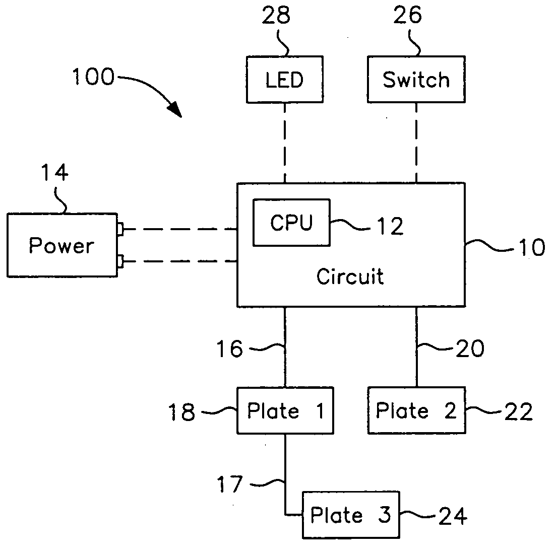
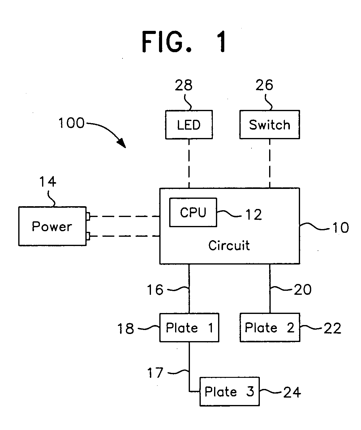
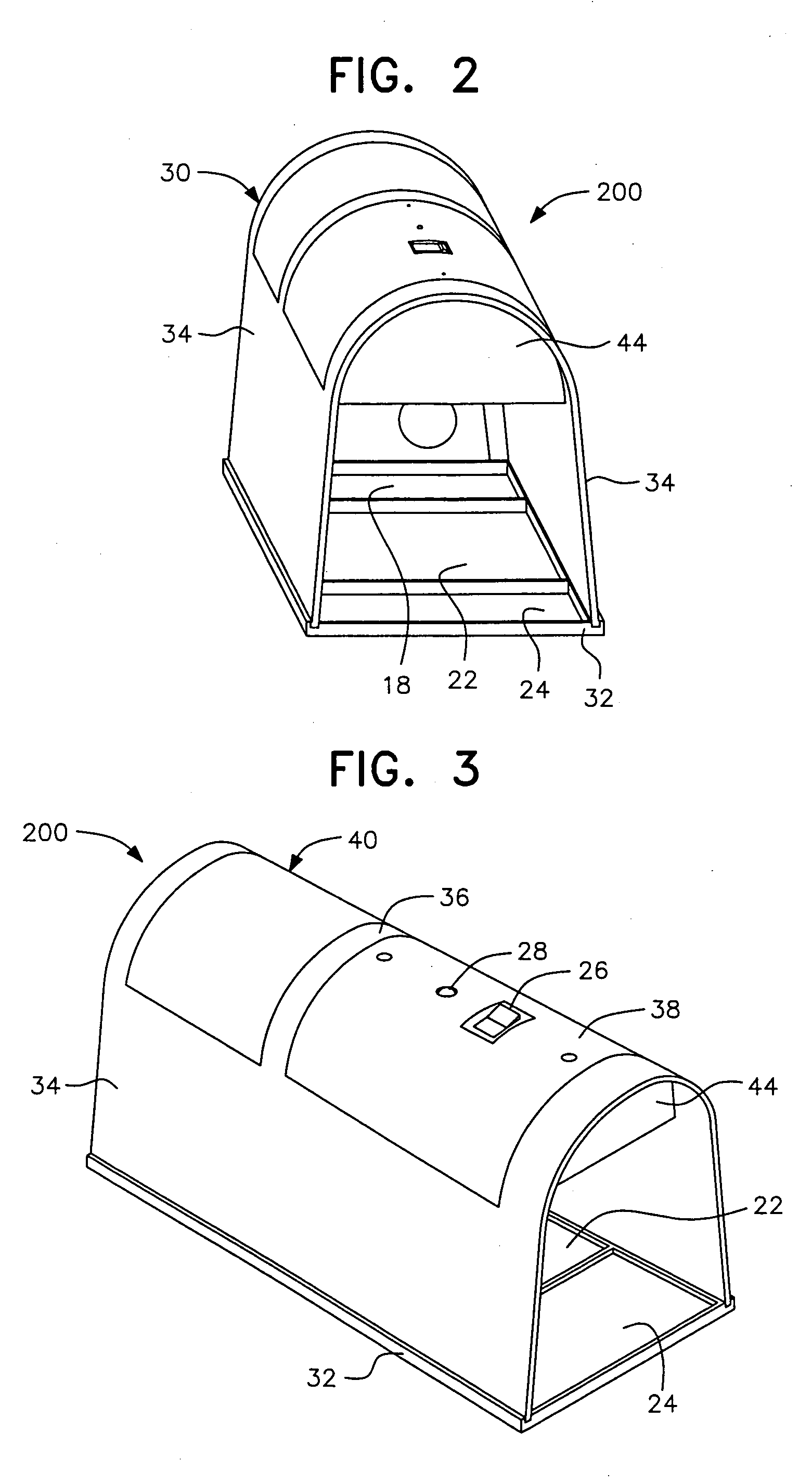
An electronic animal trap with a CPU-controlled, rearming, three-killing-plate configuration and extended killing cycle for trapping and exterminating larger rodents such as rats. The high-voltage output circuit is connected to a pair of killing plates which are activated with a high-voltage pulse train for a killing cycle when a pest of known impedance is sensed across said pair of plates. A third killing plate, electrically coupled to a first plate of said pair of plates, is brought to the voltage level of the first plate within approximately 1 msec of circuit activation for increased kill and escape-prevention capabilities.

Description

[0001] This application is entitled to and hereby claims the priority of co-pending U.S. Provisional application, Ser. No. 60 / 499,371 filed Sep. 3, 2003.BACKGROUND OF THE INVENTION [0002] 1. Field of the Invention [0003] The invention relates to electric or electronic animal traps, and relates more particularly to an animal trap adapted to catch and electrocute a targeted animal, and also to rearm in the event the continuing presence of the animal is not detected upon completion of a killing cycle. [0004] 2. The Prior Art [0005] A number of animal traps have been developed which include structural devices to trap an animal and prevent its escape, along with electric or electronic components which act to kill the trapped animal. [0006] One such device is found in copending application, Ser. No. 10 / 043,161, filed Jan. 14, 2002 (the '161 application), now U.S. Pat. No. 6,609,328, which is hereby incorporated by reference in its entirety. The trap disclosed in the '161 application is vi...

Claims


Application Information

Patent Timeline
IPC IPC(8): A01M23/38A01M31/00
CPCA01M31/002A01M23/38
Inventor RICH, CHRISTOPHER T.HARMAN, LARRY L.ANDERSON, DAVID L.
Owner WOODSTREAM CORP
Why Eureka
Try Eureka