
OLED package structure

a technology of oled and packaging, applied in the field of display technology, can solve the problems of reducing the service life of oled devices, lack of external manufacturing process, etc., and achieves the effect of reducing the curving radius of an oled package structure, powerful moisture and oxygen blocking capability, and reducing the curving radius

Active Publication Date: 2020-01-28
WUHAN CHINA STAR OPTOELECTRONICS TECH CO LTD
View PDF7 Cites 0 Cited by
  • Summary
  • Abstract
  • Description
  • Claims
  • Application Information

AI Technical Summary

Benefits of technology

The present invention provides an OLED packaging method and structure that can reduce the curping radius of the package, allow for rollable display with reduced curving radius, and have better moisture and oxygen blocking capabilities. This results in an extended service life for the OLED package structure. The method includes the formation of a first outer bound confinement layer and then the formation of a first organic layer on the first inorganic layer. The use of an organic material with reduced viscosity helps to achieve better homogeneity and reduced thickness of the first organic layer, further reducing the curving radius of the OLED package structure. The first outer bound confinement layer also helps to block external moisture and oxygen from corroding the first organic layer. Overall, the present invention provides an OLED package structure that allows for rollable display with reduced curving radius, improved blocking of moisture and oxygen, and extended service life.

Problems solved by technology

The flexible OLED display device may readily generate cracking during a curving or folding process so as to introduce external moisture and oxygen therein thereby degrading organic light emitting materials and reducing the service life of the OLED devices.
However, the formation of the bank increases an operation step in manufacturing a substrate and often lacks the capability of blocking external moisture and oxygen.
However, the patent document lacks details concerning thickness of coating, viscosity of monomers of organic materials, and manufacturing processes.
If the coating of the organic layer is conducted with flash evaporation, ink jet printing, or slot die coating, then it is quite doubtful concerning the feasibility of forming a thin film encapsulation structure that has a homogeneous thickness and is rollable.

Method used


Image

  • OLED package structure
  • OLED package structure
  • OLED package structure

Examples


Embodiment Construction

[0048]To further expound the technical solution adopted in the present invention and the advantages thereof, a detailed description will be given with reference to the preferred embodiments of the present invention and the drawings thereof.

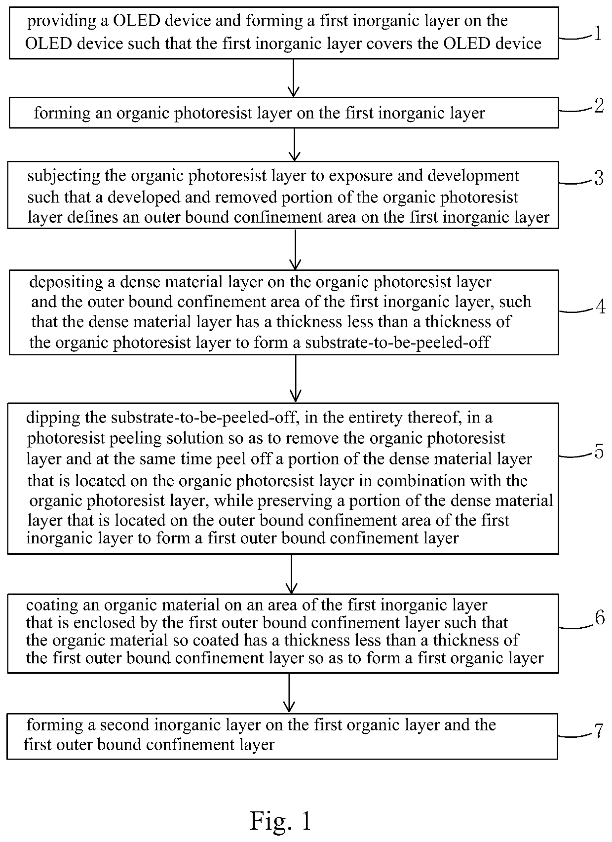
[0049]Referring to FIG. 1, the present invention provides an OLED packaging method, which comprises the following steps:

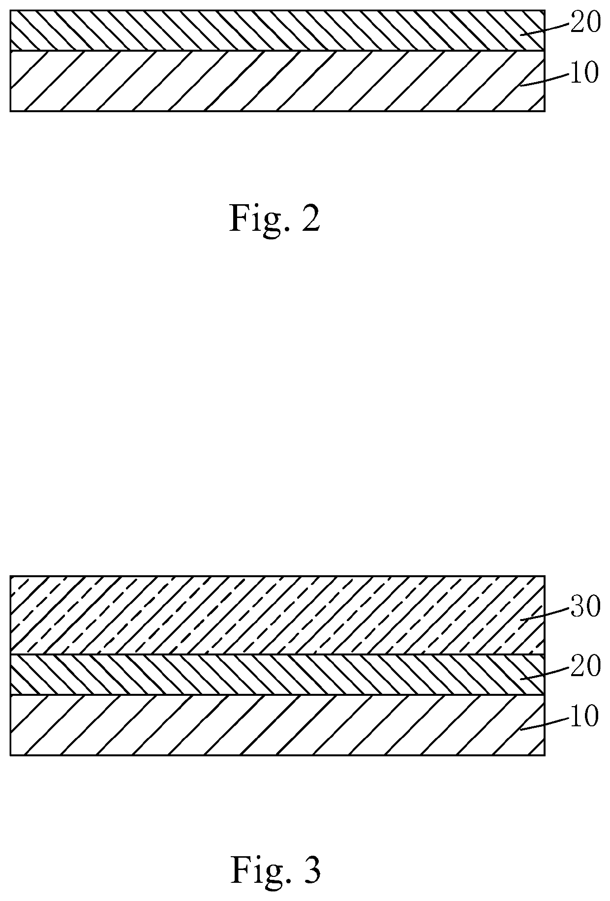
[0050]Step 1: as shown in FIG. 2, providing an OLED device 10 and forming a first inorganic layer 20 on the OLED device 10 such that the first inorganic layer 20 covers the OLED device 10.

[0051]Specifically, in Step 1, plasma enhanced chemical vapor deposition, atomic layer deposition, pulsed laser deposition, sputtering, or vapor deposition is applied to form the first inorganic layer 20.

[0052]Specifically, the first inorganic layer 20 is formed of a material comprising one or multiple ones of aluminum oxide (Al2O3), zinc peroxide (ZnO2), titanium dioxide (TiO2), silicon nitride (SiNx), silicon carbonitride (SiCNx), silicon oxid...


PUM

PropertyMeasurementUnit
thicknessaaaaaaaaaa
luminous efficiencyaaaaaaaaaa
electric fieldaaaaaaaaaa

Abstract

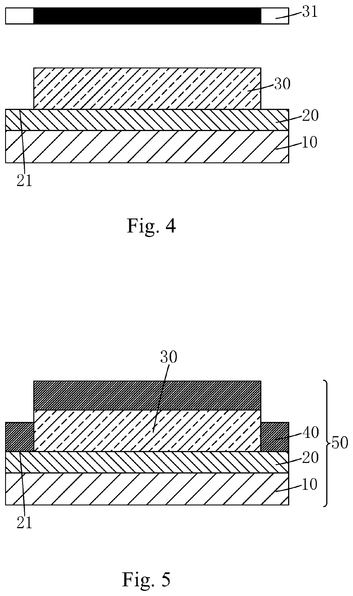
An OLED package structure includes a first outer bound confinement layer formed on an OLED device, a first outer bound confinement layer arranged on the first inorganic layer and enclosing and delimiting a confinement space, a first organic layer formed on the first inorganic layer in the confinement space, and a second inorganic layer arranged on the first organic layer and the first outer bound confinement layer, such that a peripheral portion of the second inorganic layer is positioned on and supported by the first outer bound confinement layer and a central portion of the second inorganic layer is partly received in the confinement space to have a bottom of the second inorganic layer positioned on and contacting a top of the first organic layer.

Description

CROSS REFERENCE TO RELATED APPLICATIONS[0001]This is a continuation-in-part application of co-pending patent application Ser. No. 15 / 505,116, filed on Feb. 20, 2017, which is a national stage of PCT Application Number PCT / CN2016 / 113037, filed on Dec. 29, 2016, claiming foreign priority of Chinese Patent Application Number 201611163660.7, filed on Dec. 15, 2016.BACKGROUND OF THE INVENTION1. Field of the Invention[0002]The present invention relates to the field of display technology, and more particular to an OLED packaging method and an OLED package structure.2. The Related Arts[0003]Organic light-emitting display (OLED) possesses various advantages, such as being self-luminous, low drive voltage, high luminous efficiency, short response time, high clarity and contrast, almost 180° view angle, wide range of operation temperature, and easy realization of flexible displaying and large-area full-color displaying, and is considered the most promising display device in the industry.[0004]...

Claims


Application Information

Patent Timeline
Patent Type & Authority Patents(United States)
IPC IPC(8): H01L29/08C23C14/04H01L51/56H01L51/52
CPCH01L51/5256H01L51/56C23C14/04H10K59/8731H10K50/8445H10K71/00
Inventor JIN, JIANGJIANGHSU, HSIANGLUN
Owner WUHAN CHINA STAR OPTOELECTRONICS TECH CO LTD
Learn More