Turbine component with enhanced stagnation prevention and corner heat distribution

Inactive Publication Date: 2005-03-03
SIEMENS ENERGY INC
View PDF52 Cites 0 Cited by
  • Summary
  • Abstract
  • Description
  • Claims
  • Application Information

AI Technical Summary

Benefits of technology

[0010] Aspects of the present invention relate to system for reducing flow stagnation between substantially adjacent components while also enhancing heat distribution characteristics of the components, especially at the corners and / or edges of the components so as to minimize or avoid localized hot spots. The system includes a first component and a second component. Both the first and second components are generally hollow, and component has at least two walls disposed substantially orthogonal to each other. Each of the two or more walls has an interior surface and an exterior surface.
[0012] The first and second components can be substantially adjacent such that the outer edge portions are disposed opposite and substantially parallel to each other. The first and second components can be disposed substantially laterally adjacent to each other. Alternatively, the first and second components can be disposed substantially circumferentially adjacent to each other. As a result, the adjacent outer edges reduce the stagnation of air flow around the first and second components, while the reduced thickness of the corner region provides enhanced heat transfer properties.

Problems solved by technology

Despite these measures, there are two recurring problems associated with head end plates.
One problem is that of low flow or stagnation zones substantially proximate to the head end plate.
The other problem is that of superheated fluids, such as combustion gases, lingering near the head end plates and other components; prolonged exposure to these gases can result in part failure due to high thermal loads, especially at the corners and edges of these components which can act as heat sinks.
While minimizing the likelihood of stagnation, the components 10 are nevertheless subjected to the high temperatures of combustion, and such a configuration can still result in unacceptably high thermal loads.
This design suffers from the disadvantage that it does not eliminate or reduce the stagnation zone.
While such a design helps in minimizing the stagnation zone proximate to the component, it is not always desirable to bleed cooling air, depending on the particular system at hand.
None of the previously designs have successfully addressed both problems of flow stagnation and the undesirable heat concentrations that can occur at corners and / or edges of components exposed to high temperature flow environments.

Method used


Image

  • Turbine component with enhanced stagnation prevention and corner heat distribution
  • Turbine component with enhanced stagnation prevention and corner heat distribution
  • Turbine component with enhanced stagnation prevention and corner heat distribution

Examples


Embodiment Construction

[0027] Aspects of the present invention relate to turbine components having one or more features that can avoid flow stagnation while also enhancing heat distributions at the corners and / or edges of the components to minimize or avoid localized hot spots. Aspects of the present Invention improve upon previous turbine component designs that failed to solve both problems.

[0028] Embodiments of the invention will be explained in the context of a head end plate for a turbine engine, but the detailed description is intended only as exemplary. Aspects according to the present invention can be applied to other situations in which two or more substantially adjacent components are subject to a superheated environment. Embodiments of the invention are shown in FIGS. 6-8, but the present invention is not limited to the illustrated structure or application.

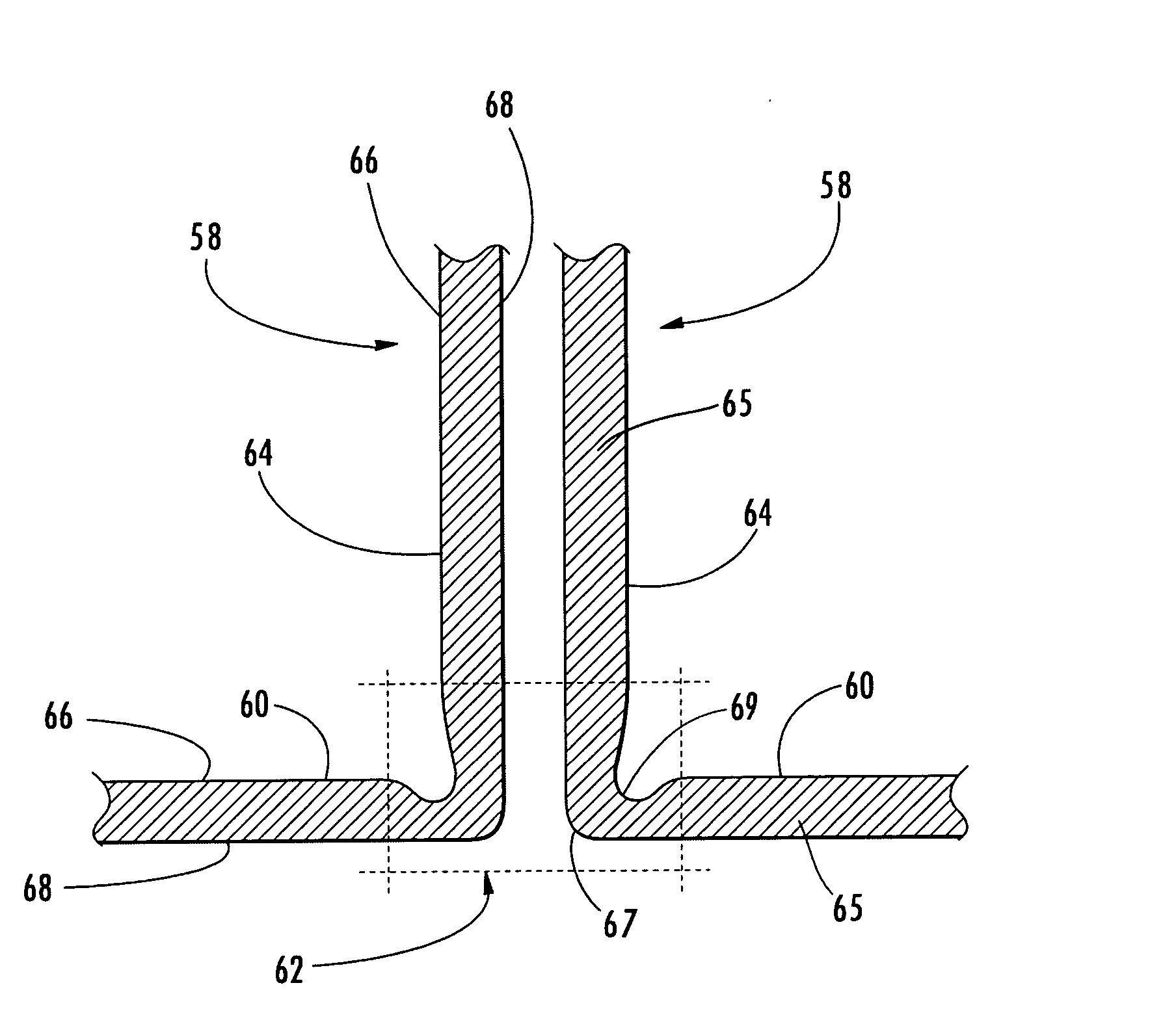
[0029] Aspects of the present invention can be applied to any generally hollow body 58 having at least two walls 60,64 disposed substantial...


PUM


Abstract

Aspects of the invention relate to a system for reducing stagnation between substantially adjacent components while providing enhanced heat distribution properties in the corners and edges of the components. Each component is generally hollow and has two wails disposed substantially orthogonal to each other. Each of the two walls includes a substantially planar region, having an associated thickness, that transitions into a corner region. The two walls join in the corner region to form an outer edge portion and an inner edge portion. The interior surface of each wall in the corner region approaches the exterior surface as the interior surface advances toward the inner edge portion such that the thickness in the corner region does not exceed the thickness of the substantially planar region. The components are substantially adjacent such that the outer edge portions are disposed opposite and substantially parallel to each other.

Description

FIELD OF THE INVENTION [0001] The invention relates in general to turbine components that operate in high temperature flow environments and, more particularly, to components configured to minimize flow stagnation near such components and to provide enhanced heat distribution characteristics. BACKGROUND OF THE INVENTION [0002] There are various applications in which one or more components can be exposed to high temperature flow conditions. For instance, many of the components in the combustor section of a turbine engine operate in such an environment. Such components can include head end plates, which are used to close off the combustor chamber, and can further be used to help centralize and align adjacent burners. An example of a head end plate 50 is shown in FIG. 3. Often, a plurality of head end plates 50 are aligned, radially or laterally, side-by-side along the combustor ring 56 as shown in FIG. 4. [0003] Usually, such components contain internal cavities or passages through whi...

Claims


Application Information

Patent Timeline
IPC IPC(8): F23R3/00F23R3/42
CPCF23R2900/00005F23R3/002
Inventor MORAES, RICARDO FERREIRA
Owner SIEMENS ENERGY INC
Why Eureka
Try Eureka