Electro-pneumatic shifting system

a technology of electric pneumatic shifting and transmission system, which is applied in the direction of gear control, belt/chain/gearing, motorcycles, etc., can solve the problems of cable breaking or extending over time, and the range of output of the engine in a motorcycle does not match the range of wheels' requirements, so as to slow down the rate of clutch engagement on startup

Inactive Publication Date: 2005-03-03
PICK DEAN
View PDF9 Cites 0 Cited by
  • Summary
  • Abstract
  • Description
  • Claims
  • Application Information

AI Technical Summary

Benefits of technology

[0011] The invention relates to an electro-pneumatic control system for a motorcycle transmission, comprising a pneumatic clutch cylinder used to disengage a clutch by pulling in a clutch lever via a clutch cylinder rod, valve means being provided to control said clutch cylinder by regulating a pressure medium flow from a pressure medium source. As per the invention said clutch cylinder is a single acting pneumatic clutch cylinder and cited valve means comprise a 3 / 2 way clutch valve controlled by an electrically operated clutch valve switch to allow said pressure medium to be introduced from said pressure medium source into one end of the clutch cylinder. The proposed shifting system makes use additionally of a 3 / 2 way launch control valve controlled by an electrically operated launch control valve switch to direct exhausting pressure medium from the clutch cylinder through a restrictor in order to slow down the rate of clutch engagement on startup.

Problems solved by technology

The characteristics of speed, torque (turning or twisting force), and power (rate or speed at which work is performed) for a typical internal combustion engine in a motor vehicle such as a motorcycle or a car usually do not match the requirements of the final propulsion component.
For example, the range of output of the engine in a motorcycle does not match the range of requirements of the wheels in contact with the road surface.
This simple standard approach has a number of disadvantages, including the cable becoming broken or extended over time, and the physical effort required to disengage the clutch lever.
As a result, the clutch may not be fully disengaged unless the driver put in significant effort, which in itself may be distracting and lead to loss of control.
The cable may also be trapped and rendered stuck against mechanical feature of the entire assembly.
Hydraulic activation has the disadvantage of a fairly slow disengagement rate.

Method used


Image

  • Electro-pneumatic shifting system
  • Electro-pneumatic shifting system
  • Electro-pneumatic shifting system

Examples


Embodiment Construction

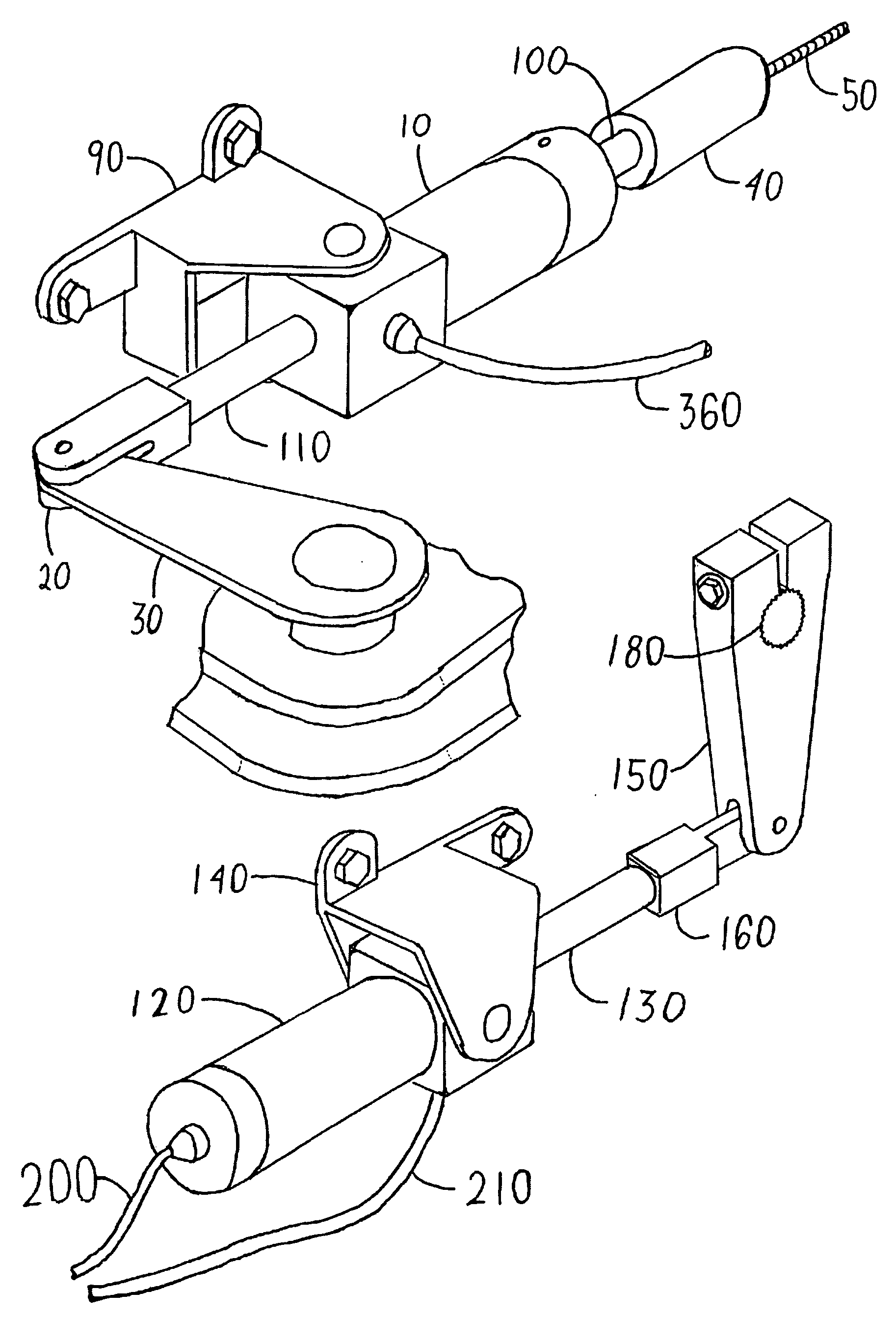
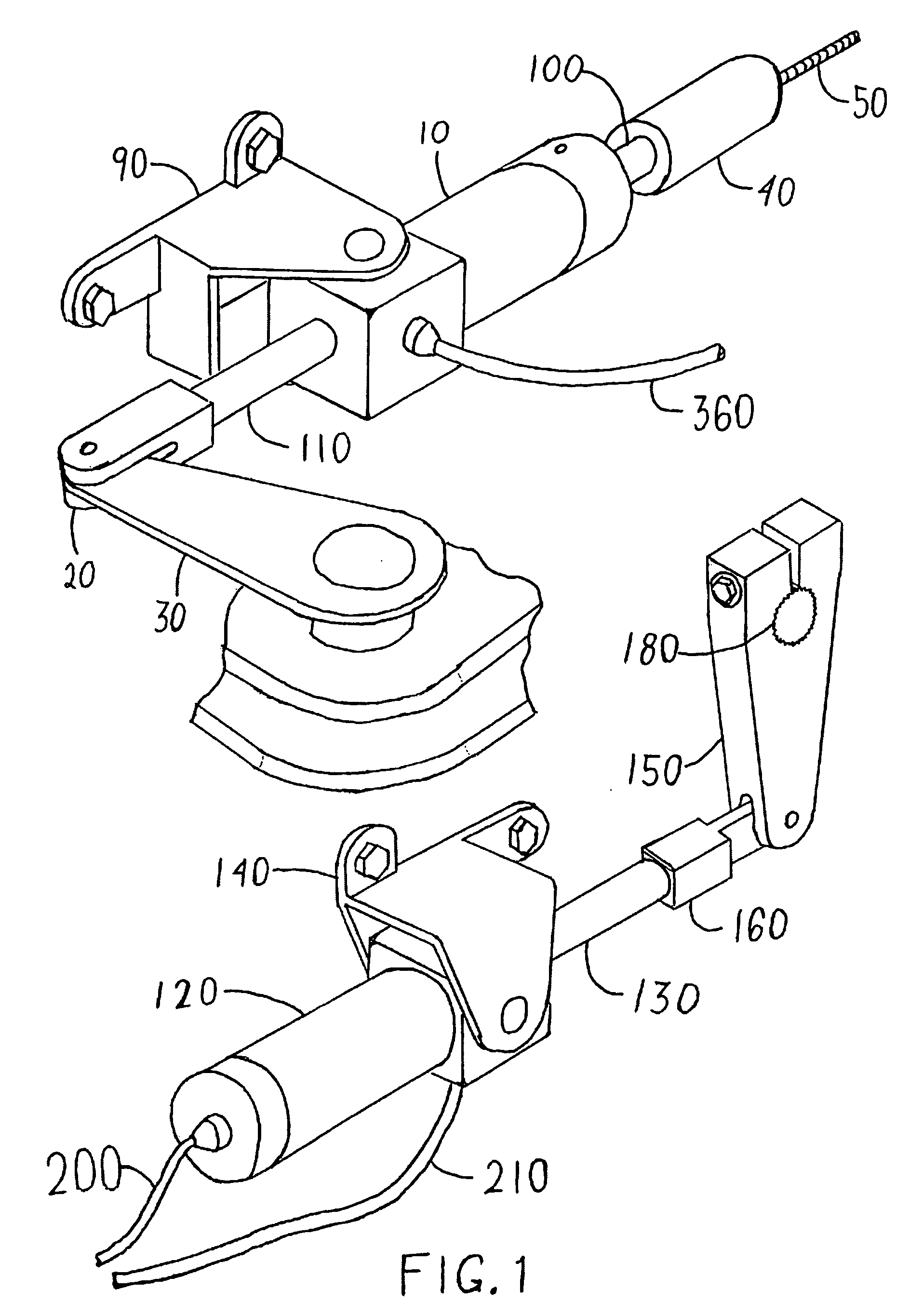
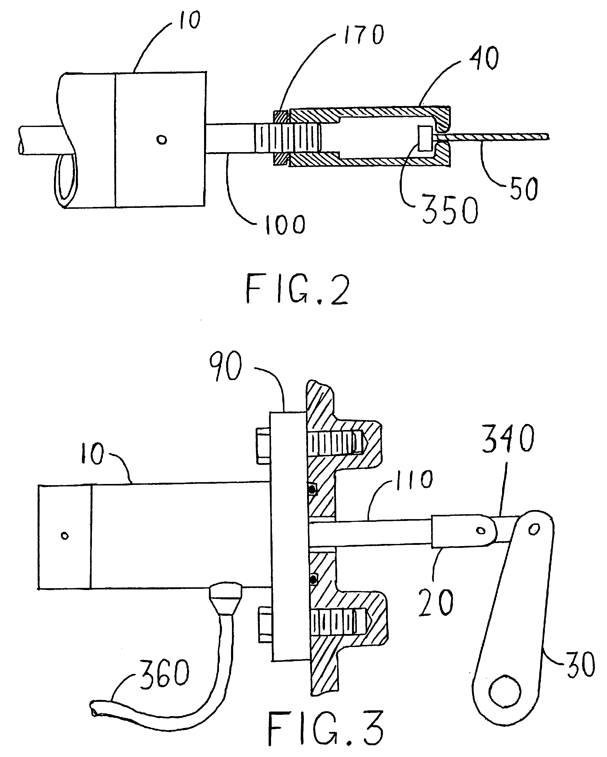
[0020]FIG. 1 is an external view of one embodiment of the invention. FIGS. 2 and 3 add further detail. The basic mechanism involves a single acting pneumatic clutch cylinder 10, standard or having a through rod 100, used to disengage the clutch by pulling in a clutch lever 30 via a clutch cylinder rod 110. The clutch cylinder rod 110 is typically connected to the clutch lever 30 by a link piece 20.

[0021] The control system can have independent and total control of the clutch; as an option, manual override may be provided for, as indicated in FIG. 1, by linking the clutch lever 30 to a clutch cable 50 by a through rod 100. During manual clutching, the clutch cable 50 and clutch cable end piece 350 pulls on a slip device 40 that pulls the through rod 100 and the clutch lever 30. On the other hand, during controlled clutching, the clutch cable 50 slides into the slip device 40 and does not apply any force to the clutch lever 30 directly or indirectly.

[0022] The clutch cylinder 10 is ...


PUM


Abstract

An electro-pneumatic control system for a motorcycle transmission. A pneumatic clutch cylinder used to disengage the clutch by pulling in a clutch lever via a clutch cylinder rod. Optionally, manual override of the clutch control may be provided for by linking the clutch lever to a clutch cable by a through rod and slip device. To change gear a pneumatic gear change cylinder, attached to the gear change lever, push-pulls lever to upshift and downshift transmission. The system is equipped with launch control that allows the motorcycle to start from a standstill.

Description

FIELD OF THE INVENTION [0001] The present invention relates to a system for controlling a motorcycle transmission, more specifically to an electro-pneumatic control system for a motorcycle transmission. BACKGROUND OF THE INVENTION [0002] The characteristics of speed, torque (turning or twisting force), and power (rate or speed at which work is performed) for a typical internal combustion engine in a motor vehicle such as a motorcycle or a car usually do not match the requirements of the final propulsion component. For example, the range of output of the engine in a motorcycle does not match the range of requirements of the wheels in contact with the road surface. A clutch, disengageably connecting the engine to the transmission, provides the means to apply and remove engine torque to the transmission's input drive shaft. [0003] A typical clutch assembly for a motorcycle includes a clutch lever located at or near the handlebar, and a clutch disengagement mechanism connected to the cl...

Claims


Application Information

Patent Timeline
Patent Type & Authority Applications(United States)
IPC IPC(8): B62M25/08F16D25/08F16D48/06F16H61/30
CPCB60K2741/225B60Y2200/12B62M25/08F16D48/066Y10T74/19251F16H61/30F16H63/46F16H2312/02F16D2500/1028B60W10/02B60W10/10B60W30/1819F16D48/08F16D2500/1117F16D2500/3026F16D2500/3146F16D2500/31493F16D2500/7041
Inventor PICK, DEAN
Owner PICK DEAN
Why Eureka
Try Eureka