

Direct injection of fuels in internal combustion engines
a technology of injection fuel and internal combustion engine, which is applied in the direction of liquid fuel feeders, machines/engines, spark plugs, etc., can solve the problems of high cost, high cost, and high cost, and achieve the effect of improving the accuracy, stability and reliability of calibration
- Summary
- Abstract
- Description
- Claims
- Application Information
AI Technical Summary
Benefits of technology
Problems solved by technology
Method used
Image

Examples
Embodiment Construction
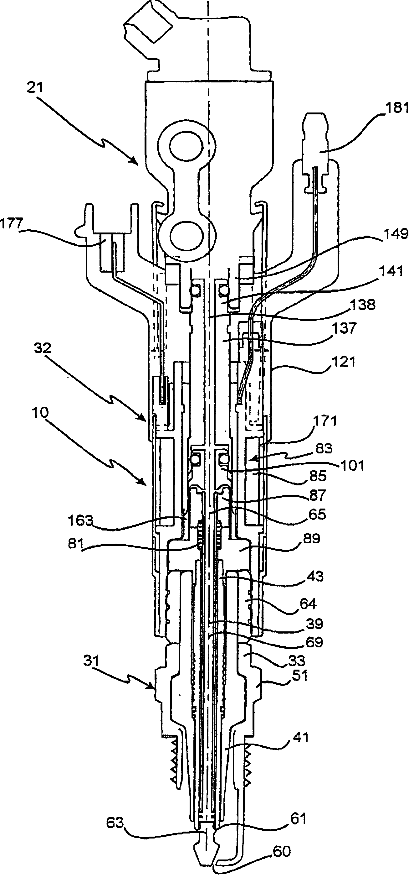
[0051] Referring to the drawings, the device 10 according to the embodiment provides a combined fuel injection and ignition means for a reciprocating-piston, spark-ignition internal combustion engine. Whilst the invention will in the main be described in relation to a four cylinder four stroke engine, it is to be appreciated that the invention is equally applicable to other engine configurations having any number of cylinders or valves, whether of the four or two stroke type.
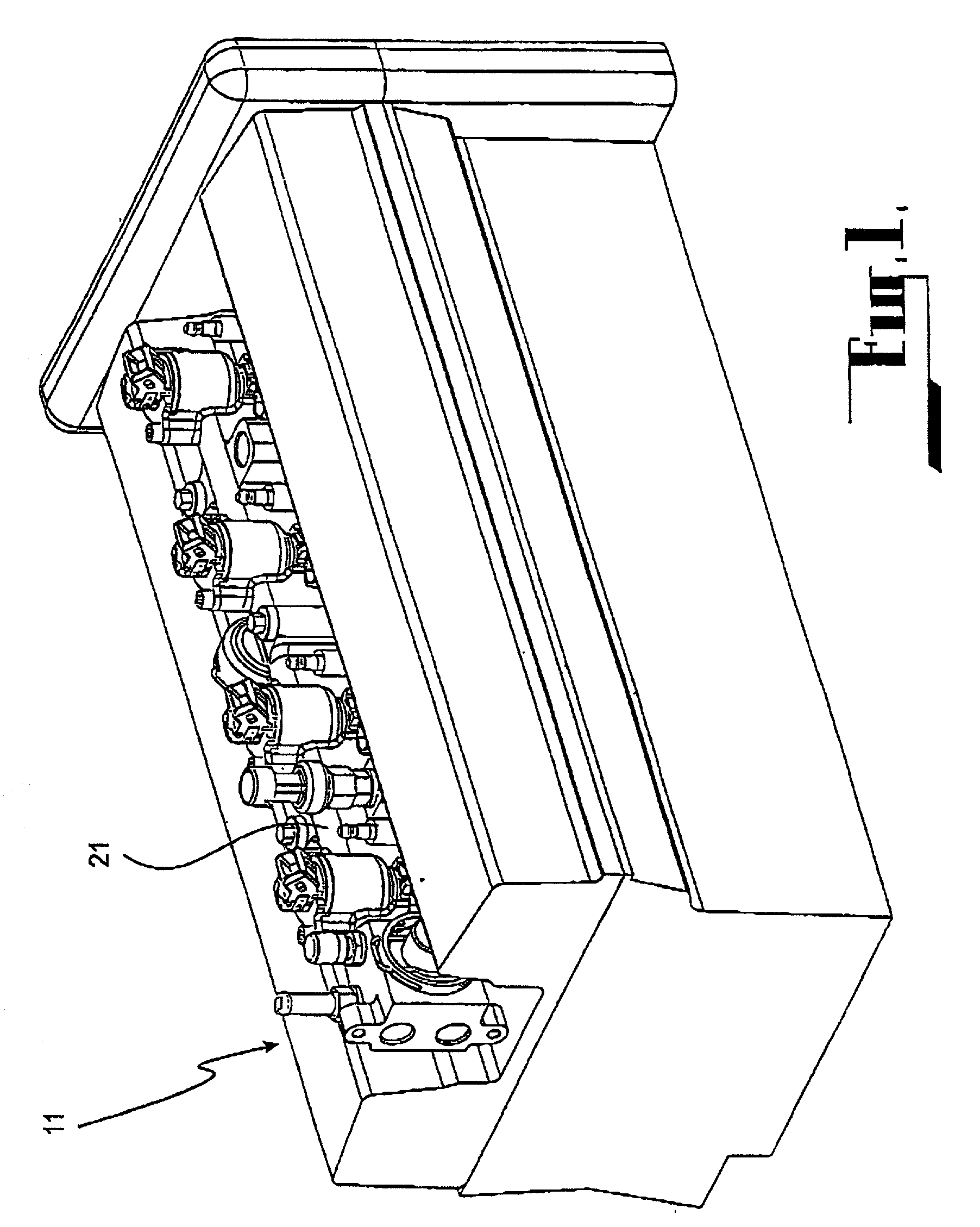
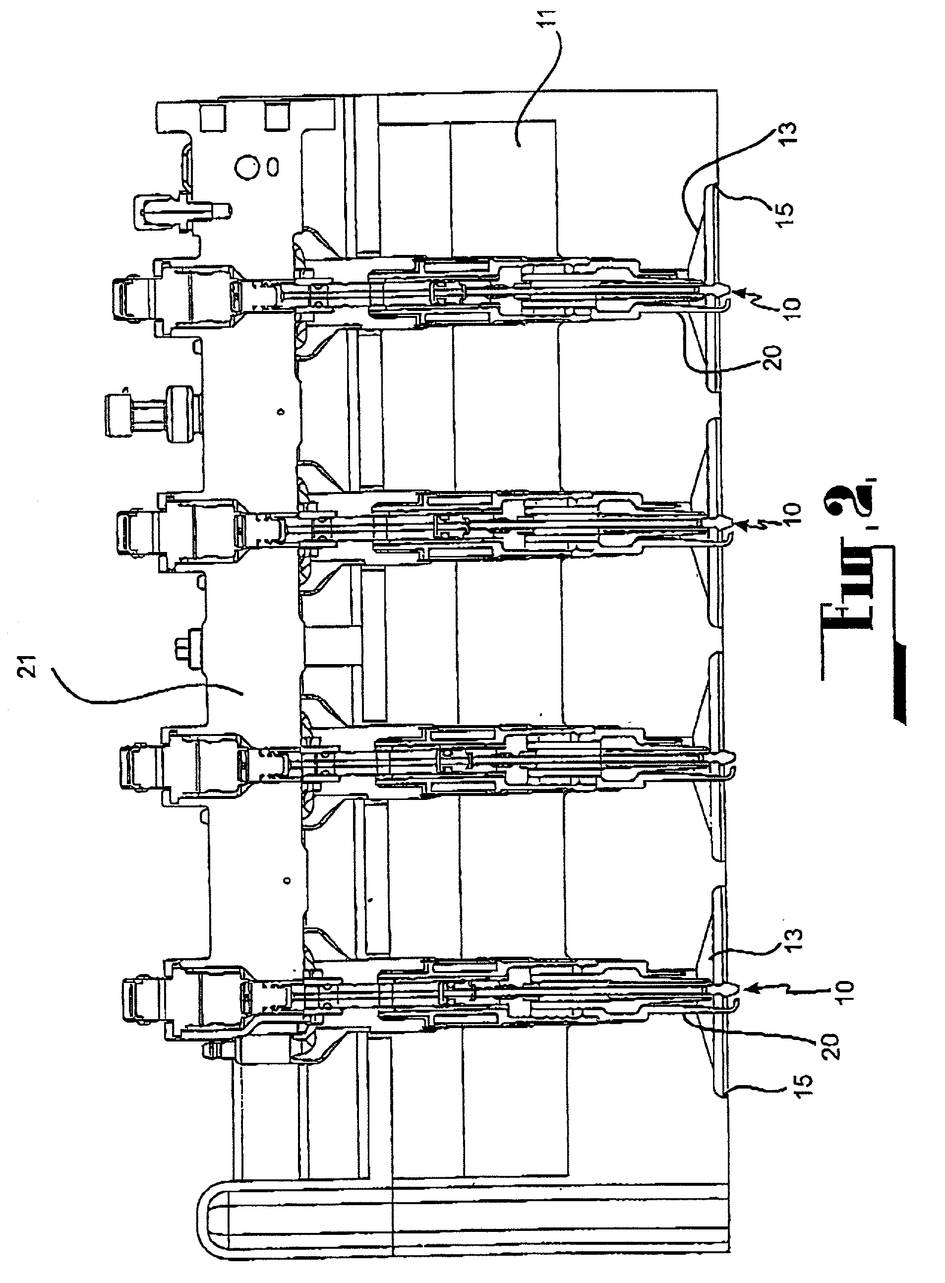
[0052] As is evident from the cylinder head 11 shown in FIGS. 1, 2 and 3, the engine referred to in this embodiment has a plurality of combustion chambers 13 into each of which fuel is delivered by way of a direct injection process utilising one of the devices 10. Each combustion chamber 13 comprises a cylinder 15 and a piston (not shown) mounted for reciprocation in the cylinder 15. The cylinder head 11 incorporates bores 20 into each of which one of the devices 10 is secured by threaded engagement, A supply r...
PUM
 Abstract
Description
Claims
Application Information