Fuel injection system

a fuel injection system and fuel injection technology, applied in the direction of fuel injection apparatus, machine/engine, charge feed system, etc., can solve the problem that the total cost of the integrated fuel injection system would typically exceed that of the ordinary unit injection or common rail system, and achieve cost reduction, simplify the overall system design, and reduce the effect of cos

Inactive Publication Date: 2005-03-03
VOLVO LASTVAGNAR AB
View PDF5 Cites 11 Cited by
  • Summary
  • Abstract
  • Description
  • Claims
  • Application Information

AI Technical Summary

Benefits of technology

[0007] A primary object of the invention is to provide a low-cost integrated fuel injection system (FIE) allowing the mechanical injection actuation and the common rail principles to be used selectively at such conditions that permit utilization of their respective advantages, and to be selectively de-activated at other conditions to avoid their respective disadvantages. The cost reduction, as compared to the known integrated FIE, is achieved by designing the system in such a way that allows the engine management system to control the mechanical actuation means of the unit injection part of the system to both directly inject fuel into the engine under high pressure, and to pressurize the common rail part of the system. This eliminates the need in a separate common rail pump thereby bringing a cost advantage and simplifying the overall system design.
[0008] Another object of the present invention is to provide a fuel injection system with a further reduced cost and an improved cylinder-to-cylinder, shot-to-shot uniformity and long-term stability of control of the nozzle opening pressure.
[0009] Still another object of the present invention is to provide a fuel injection system with an built-in (in-built), limp-home function that also allows for incorporation of advanced on-board diagnostic features in the overall control system.

Problems solved by technology

This arrangement works well but the total cost of the integrated fuel injection system would typically exceed that of an ordinary unit injection or common rail systems because of the presence of two fuel pressurization modules-unit injection plunger and the common rail pump.

Method used


Image

  • Fuel injection system
  • Fuel injection system
  • Fuel injection system

Examples


Embodiment Construction

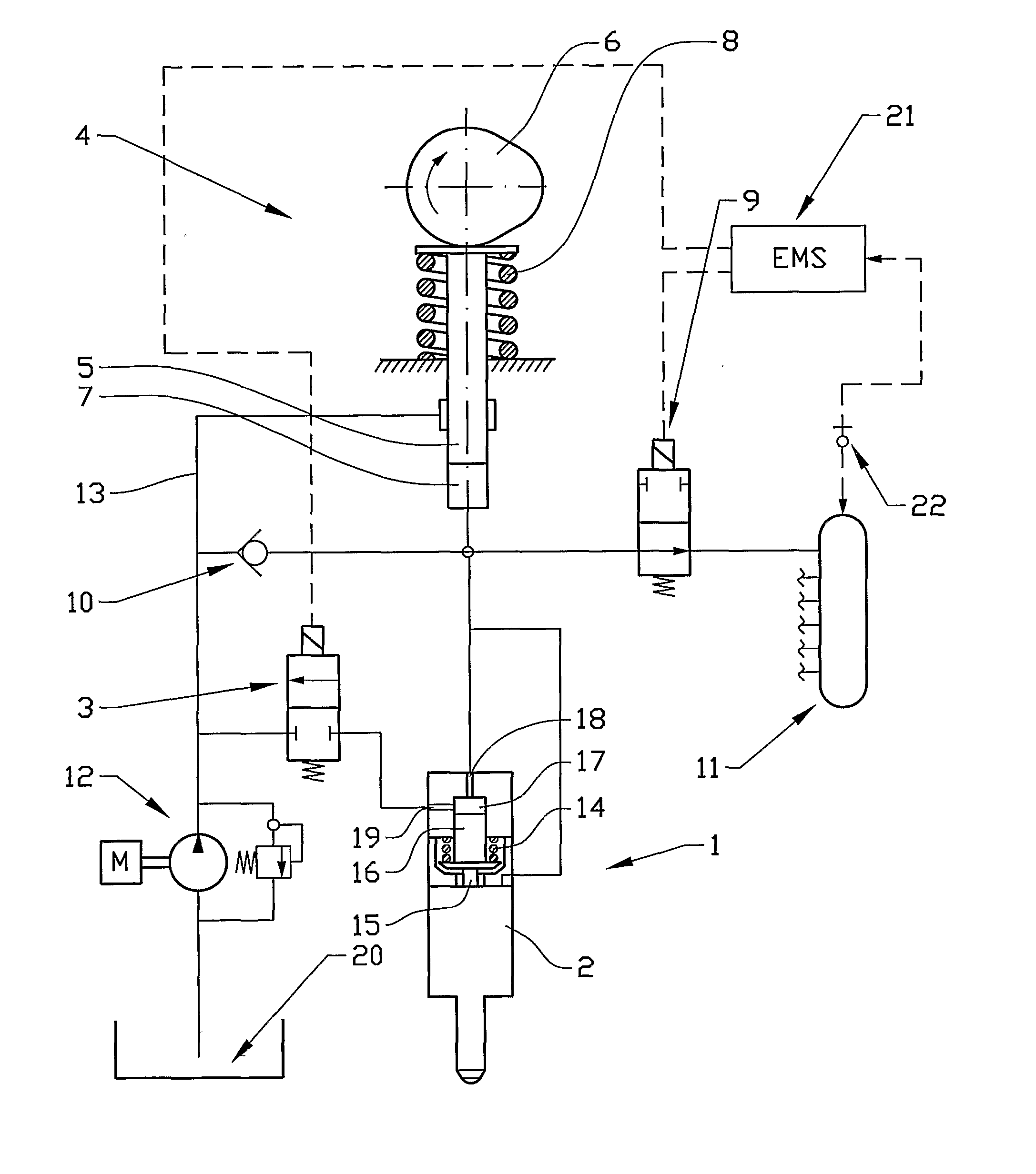
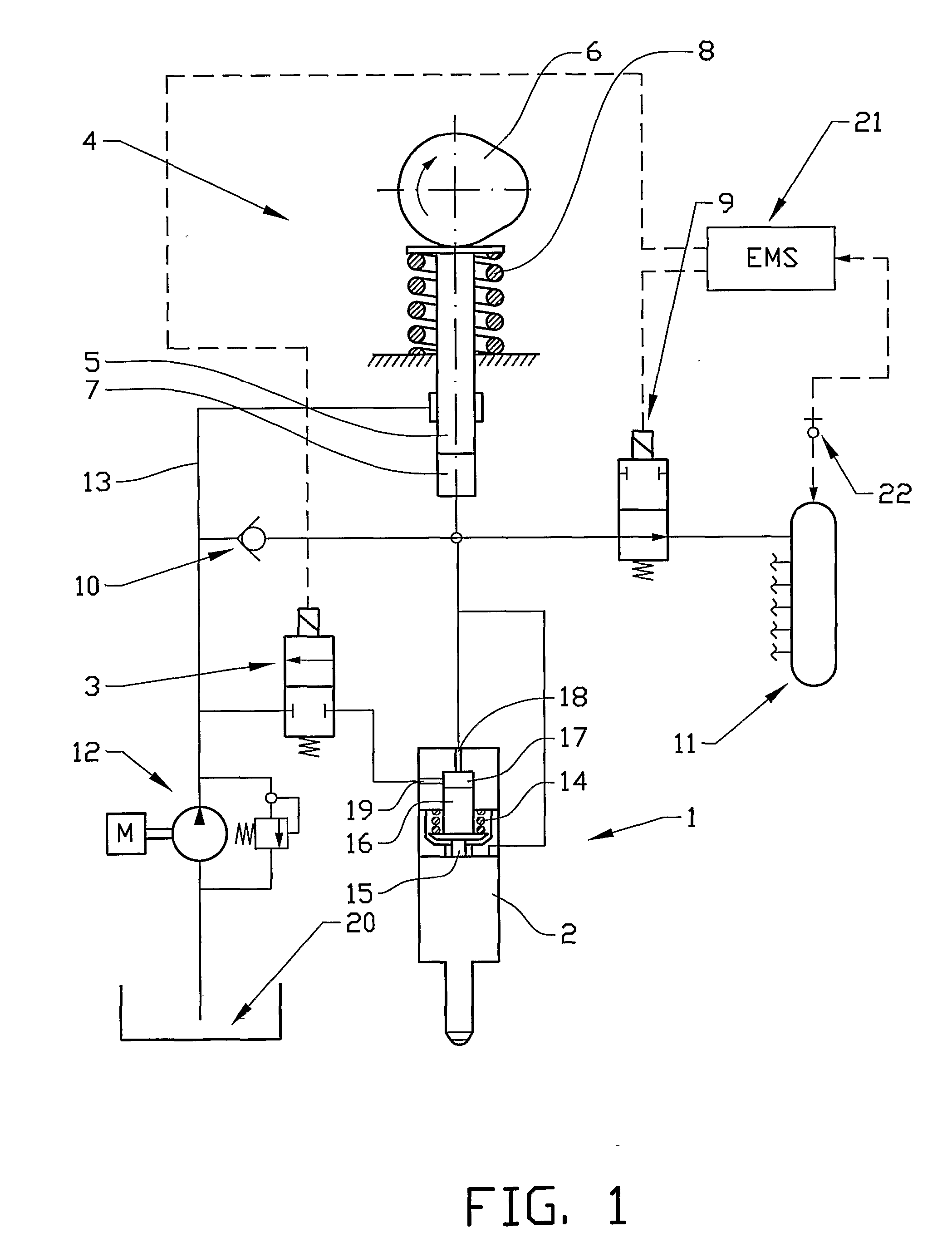
[0020] In accordance with a first embodiment of the present invention illustrated in FIG. 1, a fuel injector 1 is provided that incorporates a conventional, normally closed nozzle 2 and an electrically operated nozzle control valve (NCV) 3. A mechanically actuated means 4 for pressurizing fuel is also provided and which comprises (includes, but is not necessarily limited to) a cam-driven plunger 5 with a cam 6 and a plunger chamber 7, a return spring 8 and an electrically operated valve 9; a non-return valve 10; a common rail 11 typically serving a set of the fuel injectors and mechanically actuated means in an engine (not shown) and a maintenance means 12 for maintaining a relatively low feed pressure of the fuel in a feed line 13 and a fuel tank 20. The electrically operated valve 9 is installed between the plunger chamber 7 and the common rail 11. The inlet of the non-return valve 10 is connected to the feed line 13 and the outlet of the non-return valve is connected to the plung...


PUM


Abstract

System and method for providing a fuel injection system having a nozzle (2) with an inlet and a needle (15). A control piston (16) forms a control chamber (17) and abuts the needle such that a higher pressure in the control chamber urges the piston to close the nozzle. A cam-driven plunger (5) forms a plunger chamber (7) connected to the inlet of the nozzle. The system also has a common rail (11) for fuel, a feed line (13) and an electrically operated valve (9). The valve isolates the chamber from the common rail and connects to the line while in a third position, isolates it from both the line and the common rail in a second position, and isolates it from the line and connects it to the common rail in a first position. There are also arrangements (12) for pressurizing the feed line with a relatively low fuel feed pressure and a fuel tank (20). The control chamber is connected to the common rail.

Description

CROSS-REFERENCE TO RELATED APPLICATIONS [0001] The present application is a continuation patent application of International Application No. PCT / SE03 / 00506 filed 27 Mar. 2003 which was published in English pursuant to Article 21(2) of the Patent Cooperation Treaty, and which claims priority to Swedish Application No. 0201218-5 filed 23 Apr. 2002. Said applications are expressly incorporated herein by reference in their entireties.TECHNICAL FIELD [0002] The present invention relates to apparatus and method for injecting fuel into internal combustion engines, particularly compression ignition engines. BACKGROUND OF THE INVENTION [0003] Until recently, the known electronically controlled means of injecting fuel into modern diesel engines could be divided in two functionally different types: mechanically actuated systems and common rail systems. [0004] Both of these systems have their inherent advantages and disadvantages that dictate the choice of the system for a particular applicatio...

Claims


Application Information

Patent Timeline
Patent Type & Authority Applications(United States)
IPC IPC(8): F02M45/02F02M45/04F02M47/02F02M47/04F02M51/06F02M57/02F02M59/10F02M59/36F02M63/00F02M63/02
CPCF02M45/02F02M45/04F02M47/027F02M47/043F02M51/0603F02M63/0225F02M57/02F02M59/102F02M59/366F02M63/00F02M51/061
Inventor UDD, SORENYUDANOV, SERGI
Owner VOLVO LASTVAGNAR AB
Why Eureka
Try Eureka