[0018] In consideration of the conventional problems described above, a first object of the present invention is to provide a solder ball supplying method and a solder ball supplying device with which individual solder balls are reliably separated and supplied, even if the solder balls are small in size and the separation characteristics between the solder balls worsen due to
static electricity. In addition, a second object of the present invention is to provide a solder ball supplying method and a solder ball supplying device with which it is possible to easily remove solder balls without needing to disassemble the solder ball supplying device itself if jamming of solder balls develops.
[0019] The present invention is made based upon the finding that solder balls whose separation characteristics have worsened due to
static electricity can easily be separated provided that the separation of the solder balls is forcibly performed by an external force, not only by the weight of the solder balls themselves. In addition, the present invention is made based upon the finding that the solder balls can be removed when a solder ball jam occurs within a supply path provided that air is fed within the supply path.
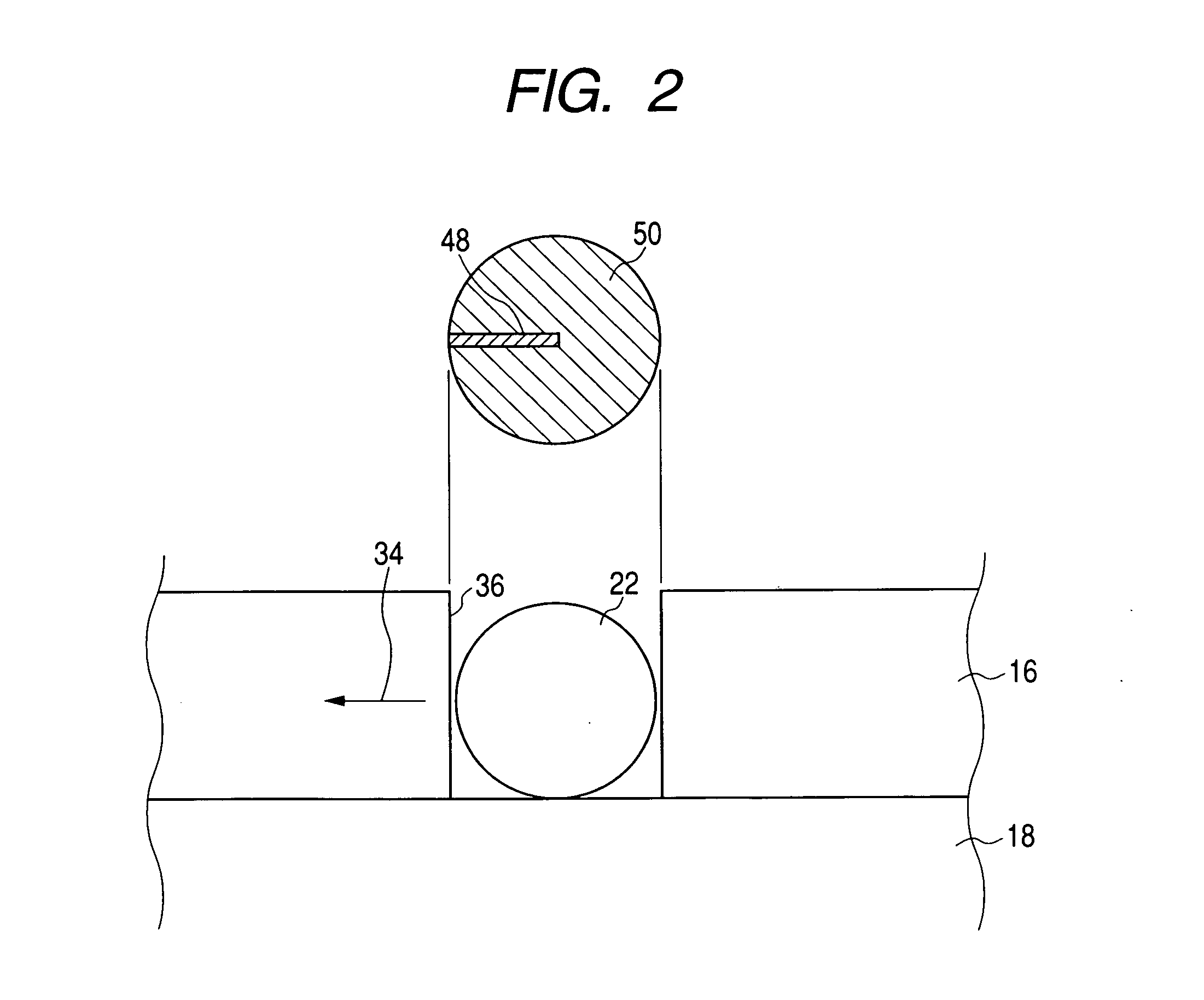
[0029] The solder ball suction path discussed here is formed within a projected region on a lower block which is situated inside of the receiving hole at a position where a solder ball is taken in, and which surrounds a rolling trajectory of the solder ball that has been taken into the receiving hole. Accordingly, the lowest point of the solder ball does not interfere with the solder ball suction path, even if the ball separator is made to slide. That is, the lowest point of the solder ball is always in rolling contact with a surface of the lower block on which the ball separator slides, and the height of the ball is maintained as constant. Therefore, it is possible to prevent a situation where the solder ball and the vicinity of an end of the solder ball suction path interfere with each other due to a step formed therebetween, causing defects such as the solder ball being caught in the step.
[0030] In addition, it is possible to increase the pressure within the hopper (
internal pressure) because the gas supplying means is connected to the upper block. Accordingly, it becomes possible to
push out the solder ball from the hopper side to the receiving hole, and introduction of the solder ball into the receiving hole can be made more reliable together with the suction from the solder ball suction path. It should be noted that it becomes possible to prevent oxidation of the solder balls within the hopper by using an
inert gas, typically
nitrogen gas or the like, for the gas that is supplied from the gas supplying means. Further, it becomes possible to agitate the solder balls within the hopper when swinging means is provided to the upper block, and introduction of the solder ball into the receiving hole can be made more reliable together with the suction from the solder ball suction path.
[0031] It should be noted that the solder balls can be aligned prior to being introduced into the receiving hole by inserting an intermediate block between the upper block and the ball separator. It thus becomes possible to reliably introduce the solder ball into the receiving hole. The solder balls that are located within the solder ball introduction path do not protrude out form the intermediate block because the plate thickness of the intermediate block is set to an integer multiple of the
diameter of the solder balls. Accordingly, the solder balls located within the solder ball introduction path can be prevented from interfering with the ball separator side, that is, with an edge portion of the receiving hole. Jamming due to the solder ball becoming caught in the edge portion can thus be prevented.
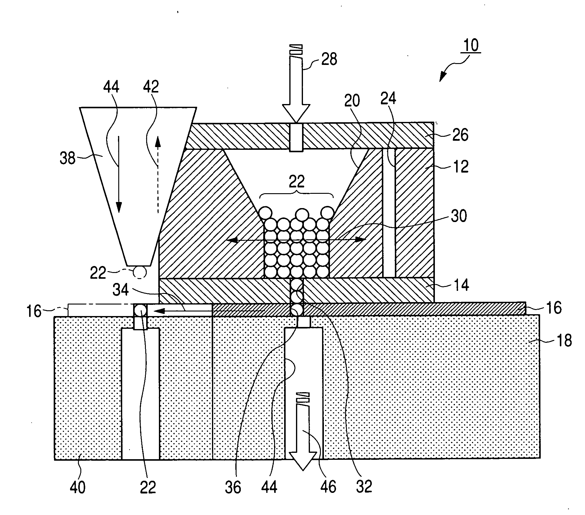
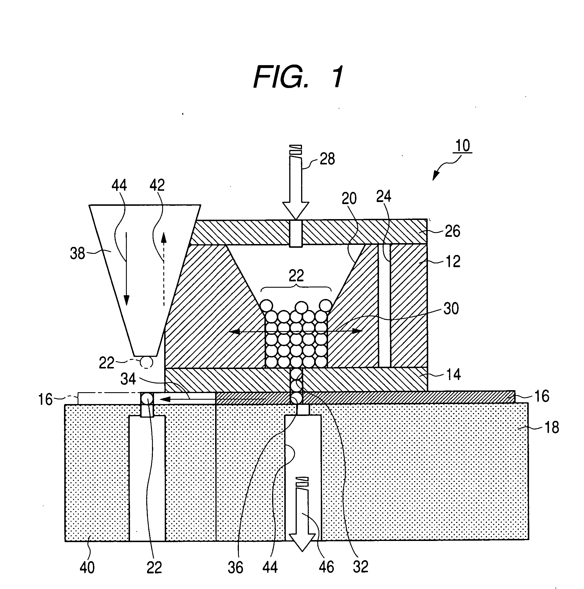
[0033] According to the present invention as discussed above, the solder ball supplying device has the upper block in which the hopper for introducing the solder ball is formed, the lower block, and the ball separator sandwiched between the two blocks and having the receiving hole into which the solder ball is taken in from a bottom portion of the hopper. The ball separator sends the solder ball held in the receiving hole out to an external portion of the blocks by sliding. The solder ball suction path is formed within a projected region on a lower block which is situated inside of the receiving hole at the position where the solder ball is taken in and which surrounds the rolling trajectory of the solder ball that has been taken into the receiving hole. The solder ball is forcibly introduced into the receiving hole from the hopper. Accordingly, even if the solder balls are small in size, and the separation characteristics of the solder balls worsen due to static
electricity, it becomes possible to reliably separate and supply each of the solder balls. The cleaning path is provided by the side of the hopper in the upper block, and air is fed to a path extending from the upper block to the lower block via the cleaning path. Therefore, even when a solder ball jam occurs, for example, the solder ball can be easily removed without needing to disassemble the solder ball supplying device itself.

