Light emitting apparatus

Inactive Publication Date: 2005-03-03
AU OPTRONICS CORP
View PDF14 Cites 55 Cited by
  • Summary
  • Abstract
  • Description
  • Claims
  • Application Information

AI Technical Summary

Benefits of technology

[0009] In view of the foregoing, it is an object of the present invention to provide an improved light emitting apparatus

Problems solved by technology

This is another disadvantag

Method used


Image

  • Light emitting apparatus
  • Light emitting apparatus
  • Light emitting apparatus

Examples


example 1

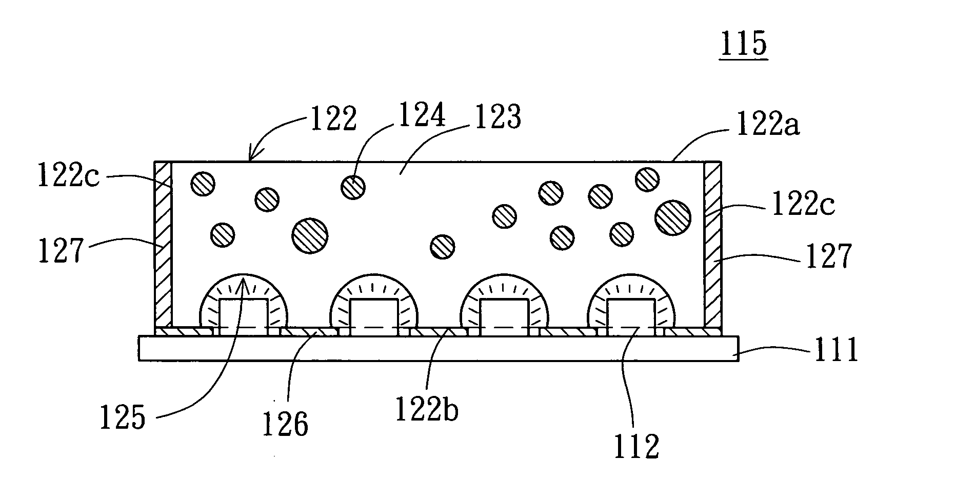
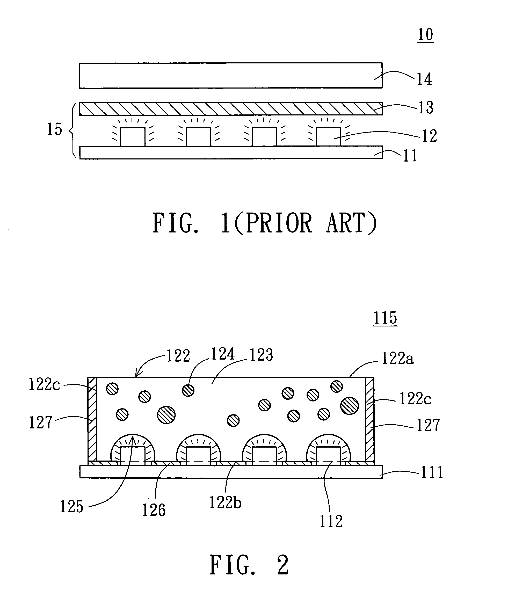
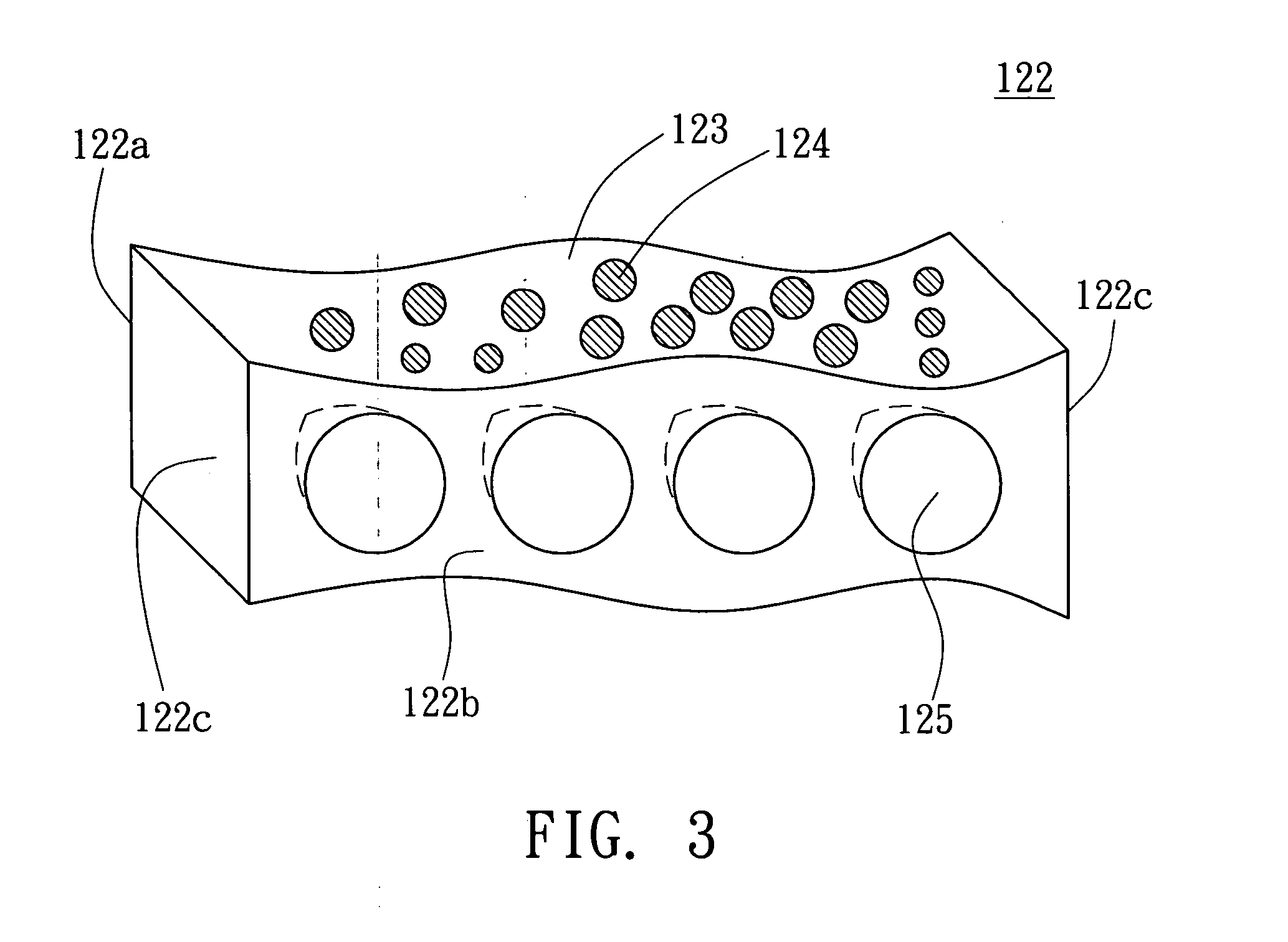
[0019]FIG. 2 is a cross-sectional view of a light emitting apparatus according to the first example in the preferred embodiment of the invention. Referring to FIG. 2, a light emitting apparatus 115 at least includes a circuit board 111, several light emitting diodes (LEDs) 112, a diffusion structure 122, a first reflective substance 126 and at least one second reflective substance 127. The circuit board 111 is preferably a printed circuit board (PCB) and the LEDs 112 include several red (R), green (G), and blue (B) LEDs. All LEDs 112 are disposed on the circuit board 111 and electrically connected with the circuit board 111.

[0020] The first reflective substance 126 is disposed on the circuit board 111 and there are several cavities formed therein so that portions of the circuit board 111 are exposed. The first reflective substance 126 can be disposed on a surface of the circuit board 111 by coating, and then the LEDs 112 are positioned on the exposed circuit board 111 and are joine...

example 2

[0026]FIG. 4 is a cross-sectional view of a light emitting apparatus according to the second example in the preferred embodiment of the invention. Referring to FIG. 4, a light emitting apparatus 415 at least includes a circuit board 111, several light emitting diodes (LEDs) 112, a diffusion structure 122, a first reflective substance 126 and at least one second reflective substance 127. Most components of the light emitting apparatus 415 here are similar to the ones of the light emitting apparatus 115 in the first example. One difference between the light emitting apparatus 415 and the light emitting apparatus 115 is the configuration of the indentations of the diffusion structure. In this example, the diffusion structure 122 includes several indentations 425 and the indentations 425 are awl-shaped, as shown in FIG. 4.

example 3

[0027]FIG. 5 is a cross-sectional view of a light emitting apparatus according to the third example in the preferred embodiment of the invention. Referring to FIG. 5, a light emitting apparatus 515 at least includes a circuit board 111, several light emitting diodes (LEDs) 112, a diffusion structure 122, a first reflective substance 126 and at least one second reflective substance 127. Most components of the light emitting apparatus 515 here are similar to the ones of the light emitting apparatus 115 in the first example. One difference between the light emitting apparatus 515 and the light emitting apparatus 115 is the configuration of the indentations of the diffusion structure. In this example, the diffusion structure 122 includes several indentations 525. The indentations 525 are oval-shaped and the cross section of the indentations 525 is an elliptic cylinder, as shown in FIG. 5.

[0028] In summary, the light emitting apparatuses 115, 415, 515 of the present invention at least o...


PUM


Abstract

A light emitting apparatus at least includes a circuit board, several light emitting diodes (LEDs), a first reflective substance, and a diffusion structure. The LEDs, including red (R), green (G), and blue (B) LEDs, are disposed on the circuit board and connected therewith, and the first reflective substance is disposed on the circuit board and having a plurality of cavities for the LEDs. The diffusion structure is disposed on the circuit board and covering the LEDs. The diffusion structure includes several indentations, a transparent main body and several diffusion beads. The indentations are formed on a bottom surface of the diffusion structure and face the LEDs to accommodate the LEDs. The diffusion beads are dispersed in the transparent main body and diffuse light emitted from the LEDs so that light emitted from R/G/B LEDs can be mixed into white light more sufficiently through the diffusion structure.

Description

[0001] This application claims the benefit of Taiwan application Serial No. 092123672, filed Aug. 27, 2003, the subject matter of which is incorporated herein by reference. BACKGROUND OF THE INVENTION [0002] 1. Field of the Invention [0003] The invention relates in general to a light emitting apparatus, and more particularly to a light emitting apparatus that mix light emitted from red (R), green (G) and blue (B) light emitting diode into white light more sufficiently. [0004] 2. Description of the Related Art [0005] A light-emitting diode (LED) is a semiconductor device that emits visible light when an electric current passes through it. The light is not particularly bright, but in most LEDs it is monochromatic, occurring at a single wavelength. The output from an LED can range from red (at a wavelength of approximately 700 nanometers) to blue-violet (about 400 nanometers). For example, LEDs which emit red (R) rays are known as R LEDs, LEDs which emit green (G) rays are known as G L...

Claims


Application Information

Patent Timeline
IPC IPC(8): H01L25/075H01L29/20H01L33/00
CPCH01L25/0753H01L2924/0002H01L2924/00
Inventor CHOU, SHEN-HONGLIU, PANG-HSUAN
Owner AU OPTRONICS CORP
Why Eureka
Try Eureka