Angular pneumatic gripper

a pneumatic gripper and angular technology, applied in the direction of gripping heads, manipulators, manufacturing tools, etc., can solve the problems of assembly faults, precision in the control of the movement of the gripper jaws, and the embodiment, etc., to achieve the effect of increasing the force of the transmission arm

Inactive Publication Date: 2005-03-03
GIMATIC SRL
View PDF8 Cites 28 Cited by
  • Summary
  • Abstract
  • Description
  • Claims
  • Application Information

AI Technical Summary

Benefits of technology

[0006] One object of this invention is to avoid the above mentioned disadvantages and drawbacks of the pneumatic angular gripper using the known technique, thanks to a new and original joining of the gripper jaws to the control piston stem, carried out by means that essentially represent an extension of the jaws in a longitudinal direction towards the stem of the piston with the advantage of an increase of the force of the transmission arm from the piston of the jaws.

Problems solved by technology

This embodiment, however, has some faults in regards to assembly and precision in the control of the movements of the gripper jaws.

Method used


Image

  • Angular pneumatic gripper
  • Angular pneumatic gripper
  • Angular pneumatic gripper

Examples


Embodiment Construction

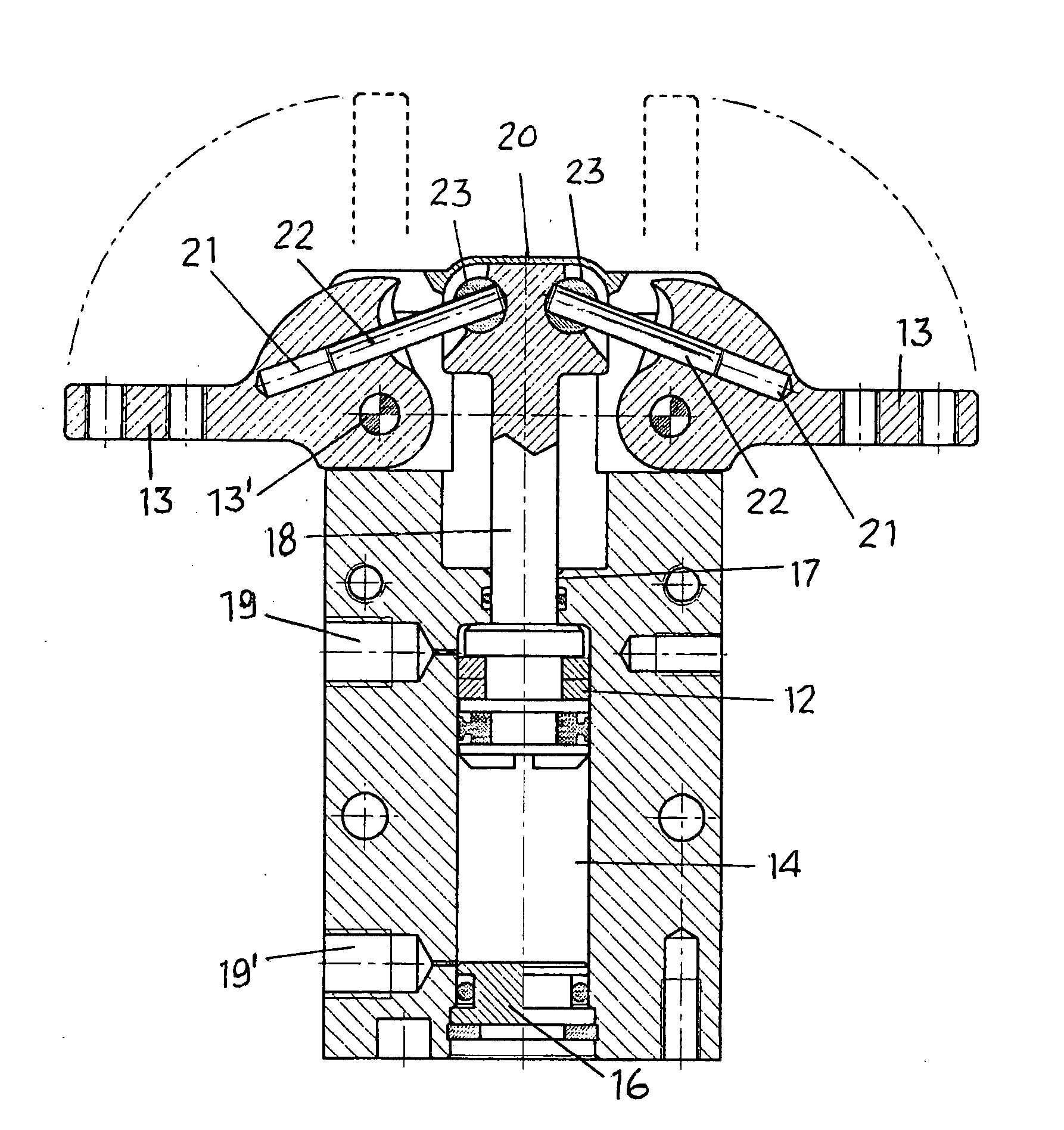
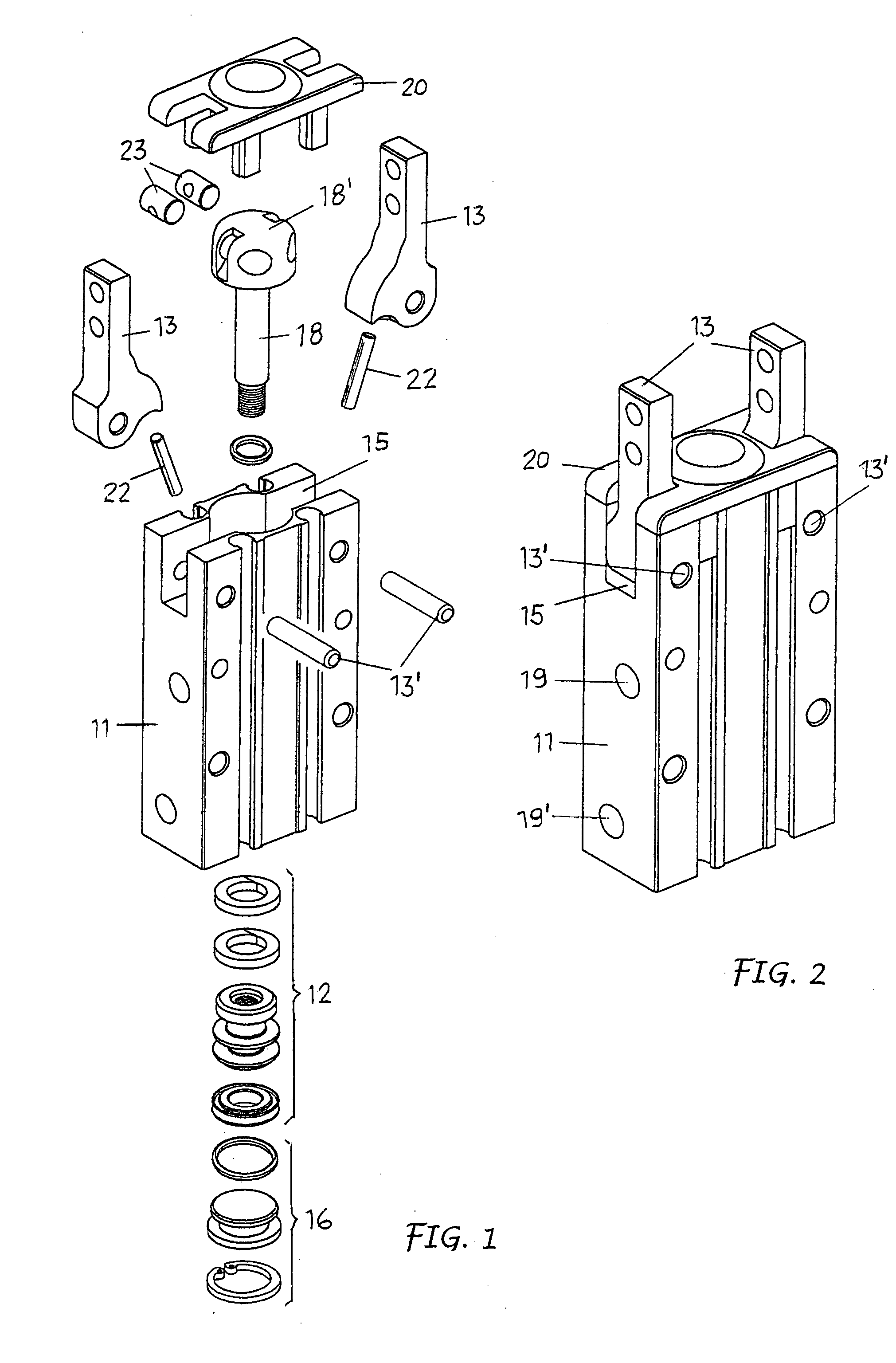
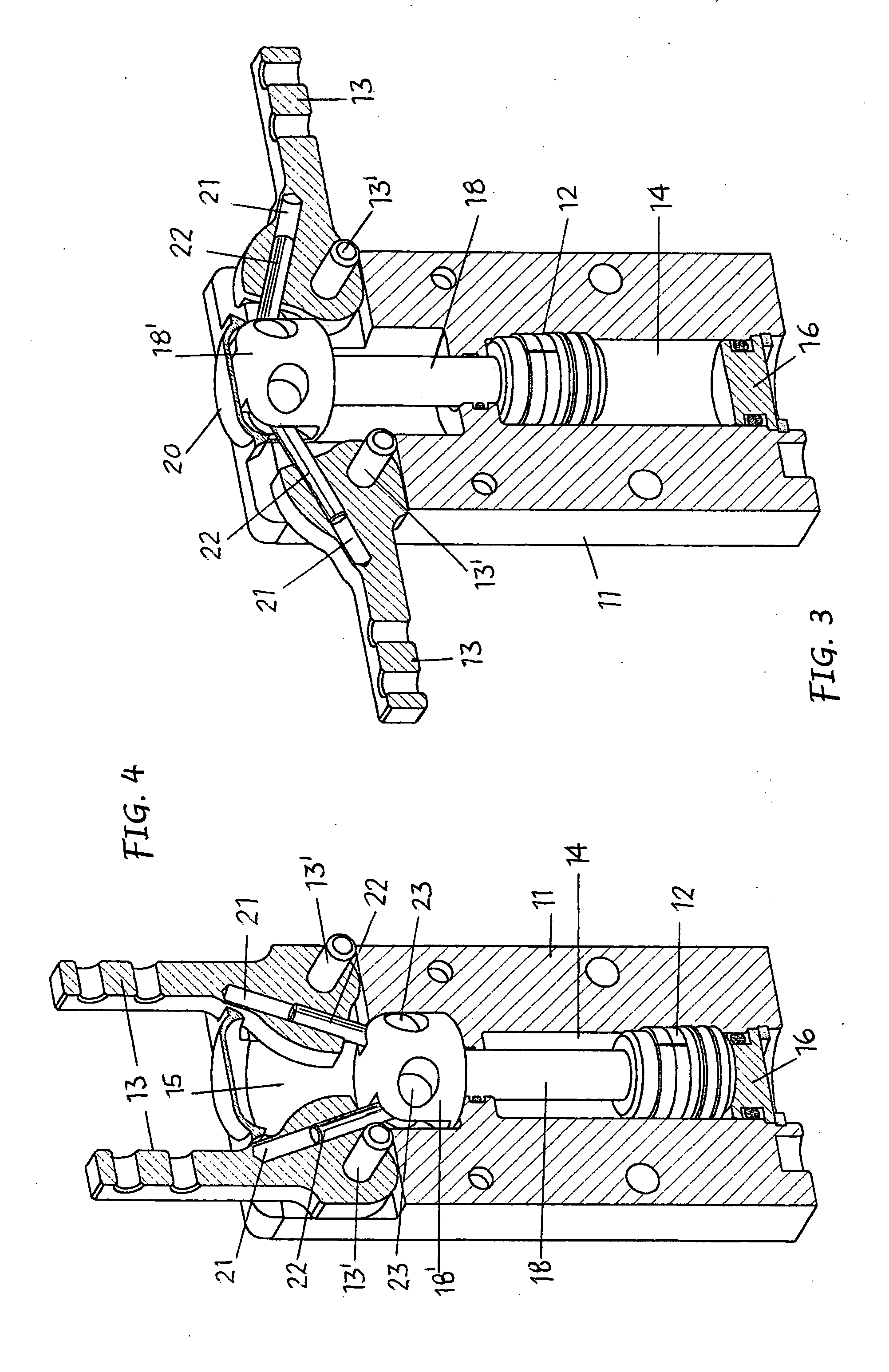
[0017] As represented, the gripper includes a gripper body 11, a control piston 12 and a couple of gripper jaws 13.

[0018] The gripper body 11 in one part forms a cylinder chamber 14 and the other part, a recess 15. At one of its ends, the chamber 14 is closed by a cover 16, whereas the opposite end opens towards the recess 15 through an intermediate hole 17.

[0019] The control piston 12 is housed and slides in the chamber 14 and is equipped with a stem 18 which passes through a seal into the intermediate hole 17 and terminates with a head 18′ on a level with the recess 15. The piston can be single acting or, as shown in the drawings, double acting. In the second case and as shown in FIGS. 5 and 6, there are two entrance / exit ports 19, 19′ at the ends of the chamber 14 of a fluid under pressure from opposite sides of the piston for the alternative movements of the latter.

[0020] The gripper jaws 13 are assembled symmetrically in the recess 15 of the gripper body from opposite sides ...


PUM


Abstract

The invention concerns a pneumatic angular gripper which includes a gripper body forming a chamber (14), a piston (12) moving alternately in said chamber, and a pair of gripper jaws (13) oscillating in opposite directions on respective rotation axes in said gripper body. Each jaw (13) is connected to the head of one piston stem (12) by means of a connecting rod (22) forming a longitudinal extension of the jaw and susceptible to angular movements in regards to the head of the stem of said piston. The connecting rod has a distal part guided and sliding in a base hole (21) formed in its respective jaw (13) and a proximal part fixed to a turning pin (23) placed on board the head of the piston stem.

Description

FIELD OF THE INVENTION [0001] This invention concerns in general the self centring devices for gripping items being machined and / or automatic handling, and refer in particular to a pneumatic gripper of the type with a pair of gripper jaws moving at an angle like levers in opposite directions to open and close by means of a single or double acting control piston. STATE OF THE THECNIQUE [0002] In the automatic items machining, handling and assembly fields, self-centring devices are well known and used, that is pneumatic grippers that include a gripper body enclosing a cylinder chamber, a piston positioned in and moving alternately in said chamber under the action of a fluid under pressure, and a couple of jaws pivoted to said body and oscillating in opposite directions on their respective rotation axes. There are means for connecting the piston to the jaws so that the linear movements of the piston are converted into angular actions of the jaws to open and close the latter. [0003] Acc...

Claims


Application Information

Patent Timeline
Patent Type & Authority Applications(United States)
IPC IPC(8): B25J15/02B25J15/08
CPCB25J15/0206
Inventor MAFFEIS, GIUSEPPE
Owner GIMATIC SRL
Why Eureka
Try Eureka