
Eureka
For R&D, Eureka makes reading and utilizing patents & technical documents easy.
Eureka AIR
Designed for self-driven R&D workflows. Generate viable solutions, solve complex R&D challenges, empower your innovation with AI.

Eureka Materials
Designed for material experts only. Revolutionize your material R&D, from search, analyze, to developing new materials.

TechResearch
Generate reliable direction feasibility study reports for your R&D in just a few steps.

TechSeek
Discover and master advanced knowledge NOW. Basics, ideas, possibilities, all at once.

TechMind
As an expert in R&D Theories, TechMind can generates customized viable solutions instantly.

TechRisk
Analyze your overall solution with one click, know your potential R&D risks in advance.

TechMonitor
Get weekly tech updates, stay abreast of the latest tech innovations and key insights.
Battery control circuit and electronic device
- Summary
- Abstract
- Description
- Claims
- Application Information
AI Technical Summary
Benefits of technology
Problems solved by technology
Method used
Image

Examples
first embodiment
[0031] First Embodiment
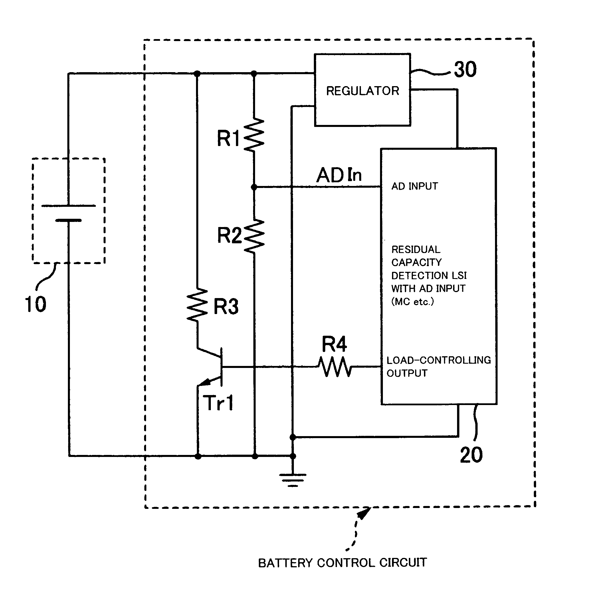
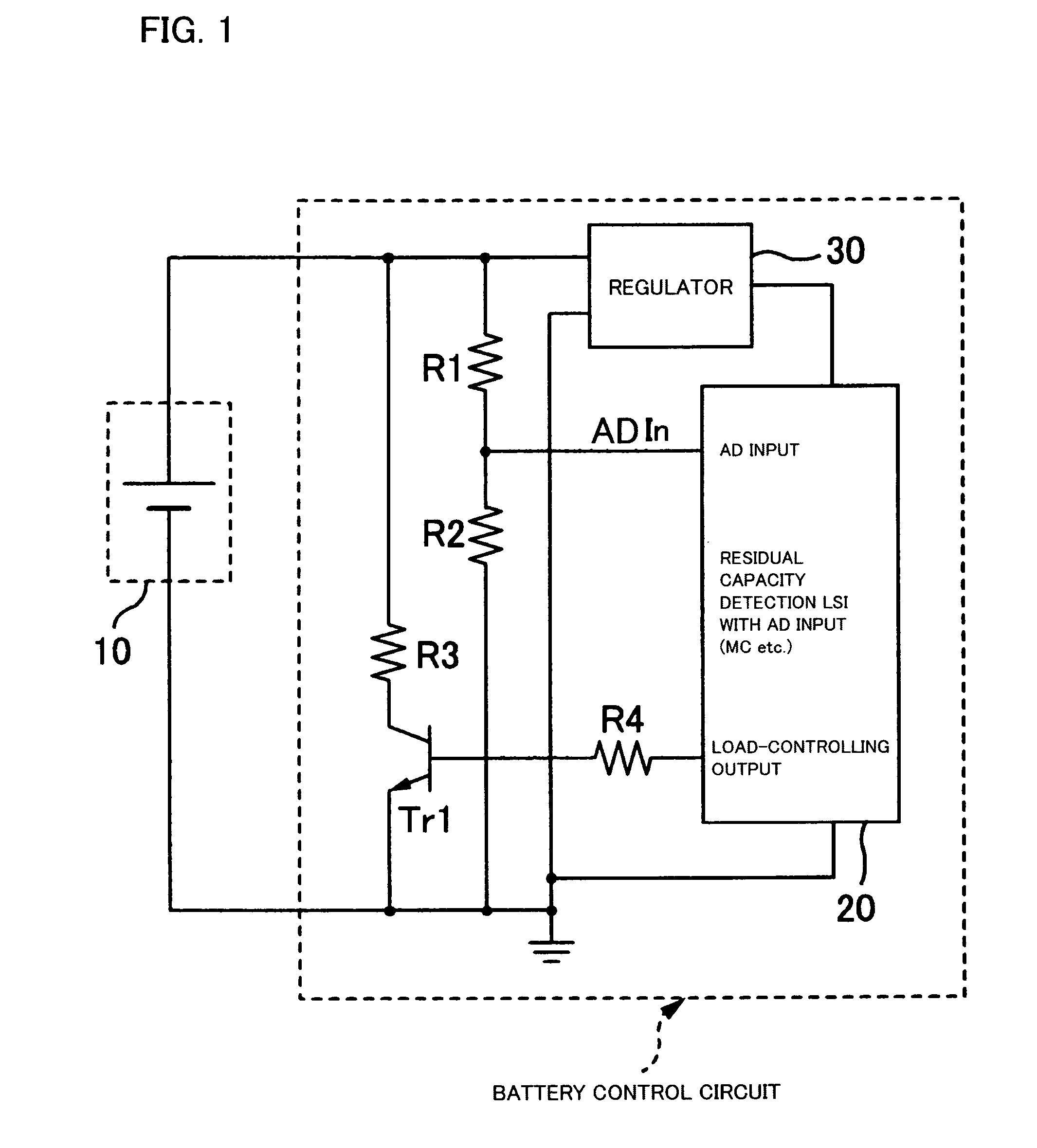
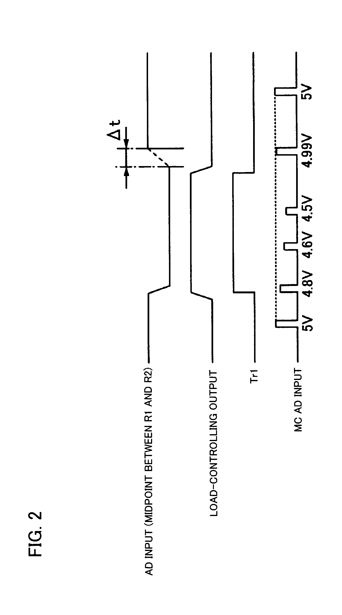
[0032] The aforementioned case where the voltage change information is the change amount of the detected battery voltage will be described. As shown in the graph of “MC AD input” of FIG. 2 described previously, the MC 20 acquires the voltage change information in a cycle based on a clock frequency for sampling. When the switching element Tr1 is OFF, the detected battery voltage is approximately 5 V. On the other hand, when the switching element Tr1 is turned on, the detected battery voltage decreases and varies around the values of 4.8 V, 4.6 V and 4.5 V. Based on these decreased values of the detected battery voltage, the battery residual capacity characteristics table stored on the ROM in the MC 20 is referred to, and the residual capacity of the battery 10 is determined.
[0033] The battery residual capacity characteristics table is a numerical data set corresponding to the graph shown in FIG. 3. In the graph (solid line) shown in FIG. 3, the change amount (...
second embodiment
[0035] Second Embodiment
[0036] The aforementioned case where the voltage change information is the voltage recovery time will be described. As shown in the graph of “MC AD input” of FIG. 2 described previously, the MC 20 acquires the voltage change information. When the switching element Tr1 is OFF, the detected battery voltage is approximately 5 V. On the other hand, when the switching element Tr1 is turned on, the detected battery voltage decreases and varies around the values of 4.8 V, 4.6 V and 4.5 V. As described previously, the time period from the time when the status of the switching element changes from ON to OFF to the time when the decreased detected battery voltage recovers to the original voltage of approximately 5 V (e.g., a voltage equivalent to 95% of 5 V) is set as the voltage recovery time. As shown in the graph of “AD input” of FIG. 2, the time period (in this drawing, “□t”) corresponding to the part of the graph represented by a broken line is the voltage recover...
PUM
 Abstract
Description
Claims
Application Information
 - R&D Engineer
- R&D Manager
- IP Professional
- Industry Leading Data Capabilities
- Powerful AI technology
- Patent DNA Extraction
Browse by: Latest US Patents, China's latest patents, Technical Efficacy Thesaurus, Application Domain, Technology Topic, Popular Technical Reports.
© 2024 PatSnap. All rights reserved.Legal|Privacy policy|Modern Slavery Act Transparency Statement|Sitemap|About US| Contact US: help@patsnap.com