Power supply circuit for vacuum fluorescent display
a technology of power supply circuit and vacuum fluorescent display, which is applied in the direction of tubes with screens, process and machine control, instruments, etc., can solve the problems of high noise, high cost and time, and light emission leakage, and achieve the effect of low nois
- Summary
- Abstract
- Description
- Claims
- Application Information
AI Technical Summary
Benefits of technology
Problems solved by technology
Method used
Image
Examples
first embodiment
[First Embodiment]
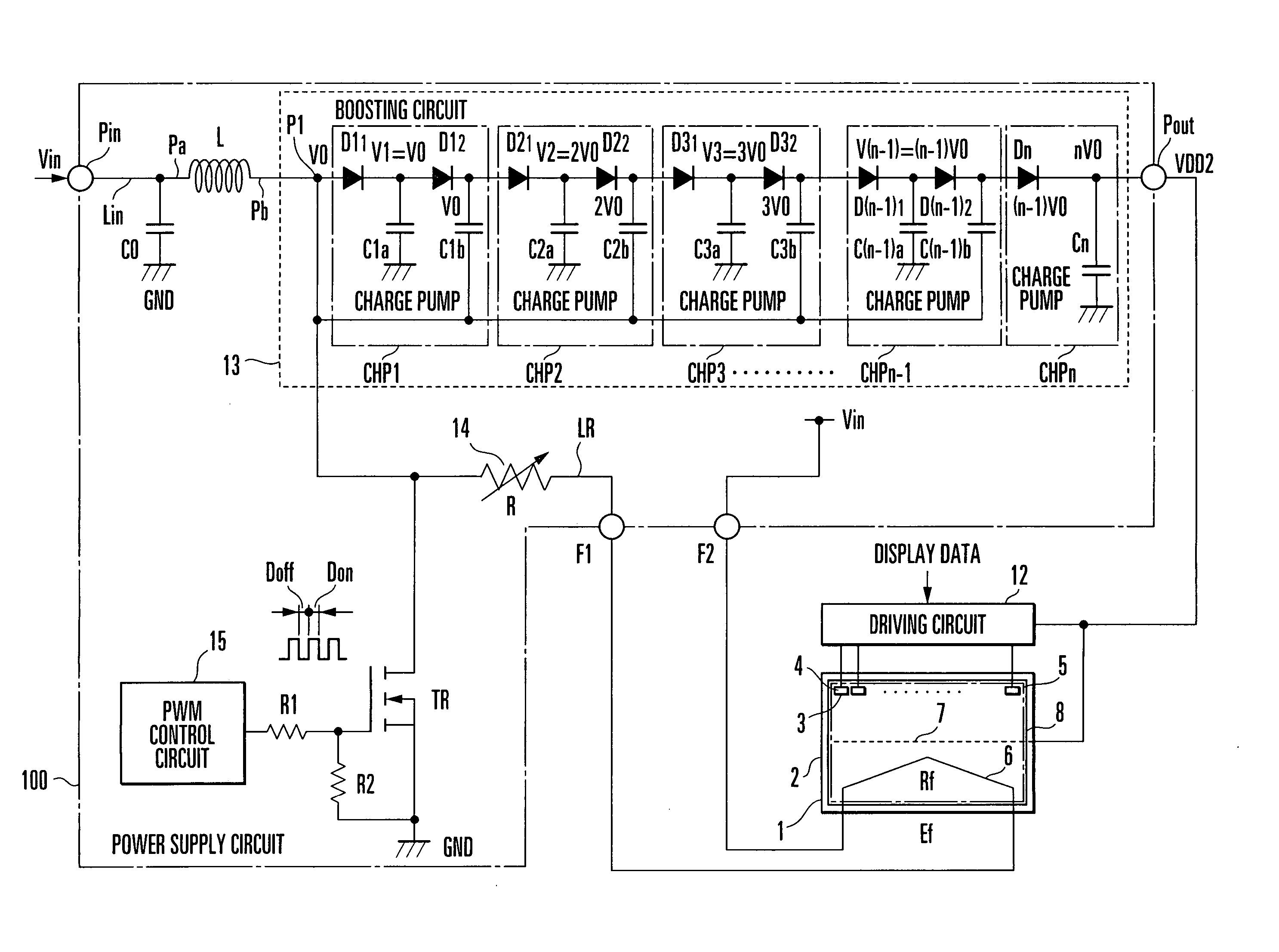
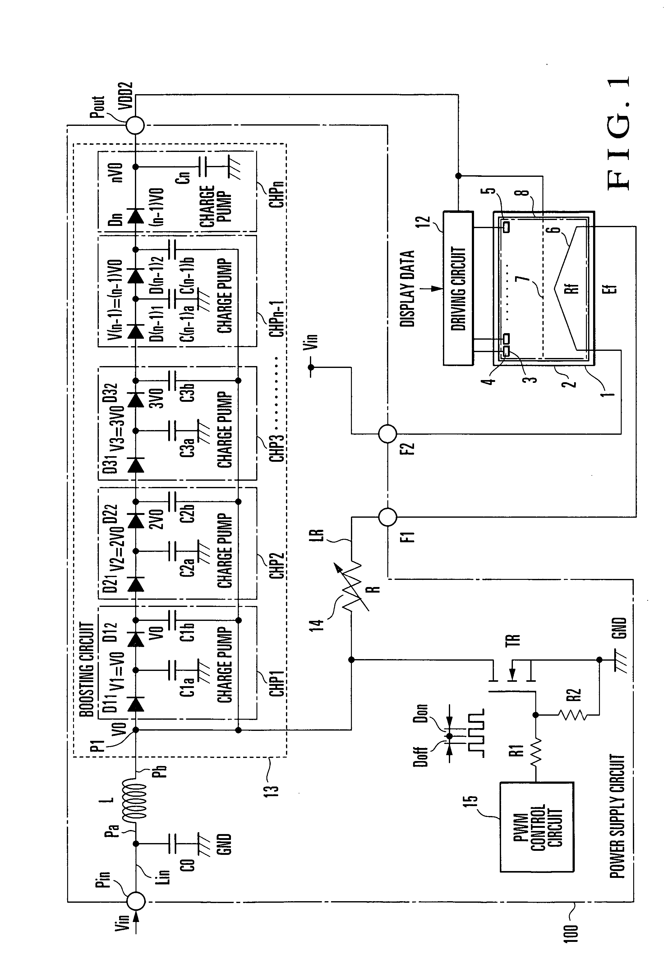
FIG. 1 shows the main part of a power supply circuit according to an embodiment (first embodiment) of the present invention. A power supply circuit 100 includes a capacitor (input smoothing capacitor) C0, a boosting coil (induction element) L, a boosting circuit 13, a switching transistor (field-effect transistor) TR, a variable resistor (voltage adjustment resistor) 14, a PWM control circuit 15, and resistors R1 and R2. The power supply circuit has an input terminal Pin, output terminal Pout, filament terminal F1 (first terminal), and a filament terminal F2 (second terminal).
An input voltage (DC voltage) Vin is applied to the input terminal Pin. A DC voltage VDD2 for the anode / grid is output from the output terminal Pout. A cathode (filament) 6 of a vacuum fluorescent display tube 1 is connected between the filament terminals F1 and F2.
In the power supply circuit 100, the boosting coil L is provided in a current path Lin between the input terminal Pin and the ...
second embodiment
[Second Embodiment]
FIG. 4 shows the main part of a power supply circuit according to another embodiment (second embodiment) of the present invention. A power supply circuit 200 includes a control circuit 16A, boosting circuit 17, and cutoff circuit 18A, and has an input terminal Pin, output terminal Pout, and filament terminals F1 and F2. A DC voltage (input voltage) Vin is applied to the input terminal Pin. A DC voltage VDD2 for the anode / grid is output from the output terminal Pout. A cathode (filament) 6 of a vacuum fluorescent display tube 1 is connected between the filament terminals F1 and F2.
The cutoff circuit 18A includes a first switch SW1, second switch SW2, resistor R, diodes D1 and D2, and capacitors C1 and C2. The switches SW1 and SW2 are connected in series between an input line Lin for a DC voltage Vin and a ground line (GND). In this series connection, the switch SW1 is located on the input line Lin side of the DC voltage Vin and the switch SW2 is located on the gr...
third embodiment
[Third Embodiment]
FIG. 8 shows an application of the power supply circuit 200 shown in FIG. 4. In a power supply circuit 300, third and fourth switches SW3 and SW4 are connected in series between an input line Lin for a DC voltage Vin and a ground line. In this series connection circuit, the switch SW3 is located on the input line Lin side of the DC voltage Vin, and the switch SW4 is located on the ground line side. A capacitor C2 is connected between a filament terminal F2 and a node PB between the switches SW3 and SW4.
A switch SW1 and the switch SW4 constitute a first switch pair, and a switch SW2 and the switch SW3 constitute a second switch pair. A control circuit 16B periodically and alternately turns on / off the first switch pair (SW1 and SW4) and the second switch pair (SW2 and SW3) in opposite directions.
That is, the control circuit 16B periodically repeats the operation of “simultaneously turning off the second switch pair (SW2 and SW3) when simultaneously turning on the...
PUM
 Abstract
Description
Claims
Application Information
 - R&D
- Intellectual Property
- Life Sciences
- Materials
- Tech Scout
- Unparalleled Data Quality
- Higher Quality Content
- 60% Fewer Hallucinations
Browse by: Latest US Patents, China's latest patents, Technical Efficacy Thesaurus, Application Domain, Technology Topic, Popular Technical Reports.
© 2025 PatSnap. All rights reserved.Legal|Privacy policy|Modern Slavery Act Transparency Statement|Sitemap|About US| Contact US: help@patsnap.com


