

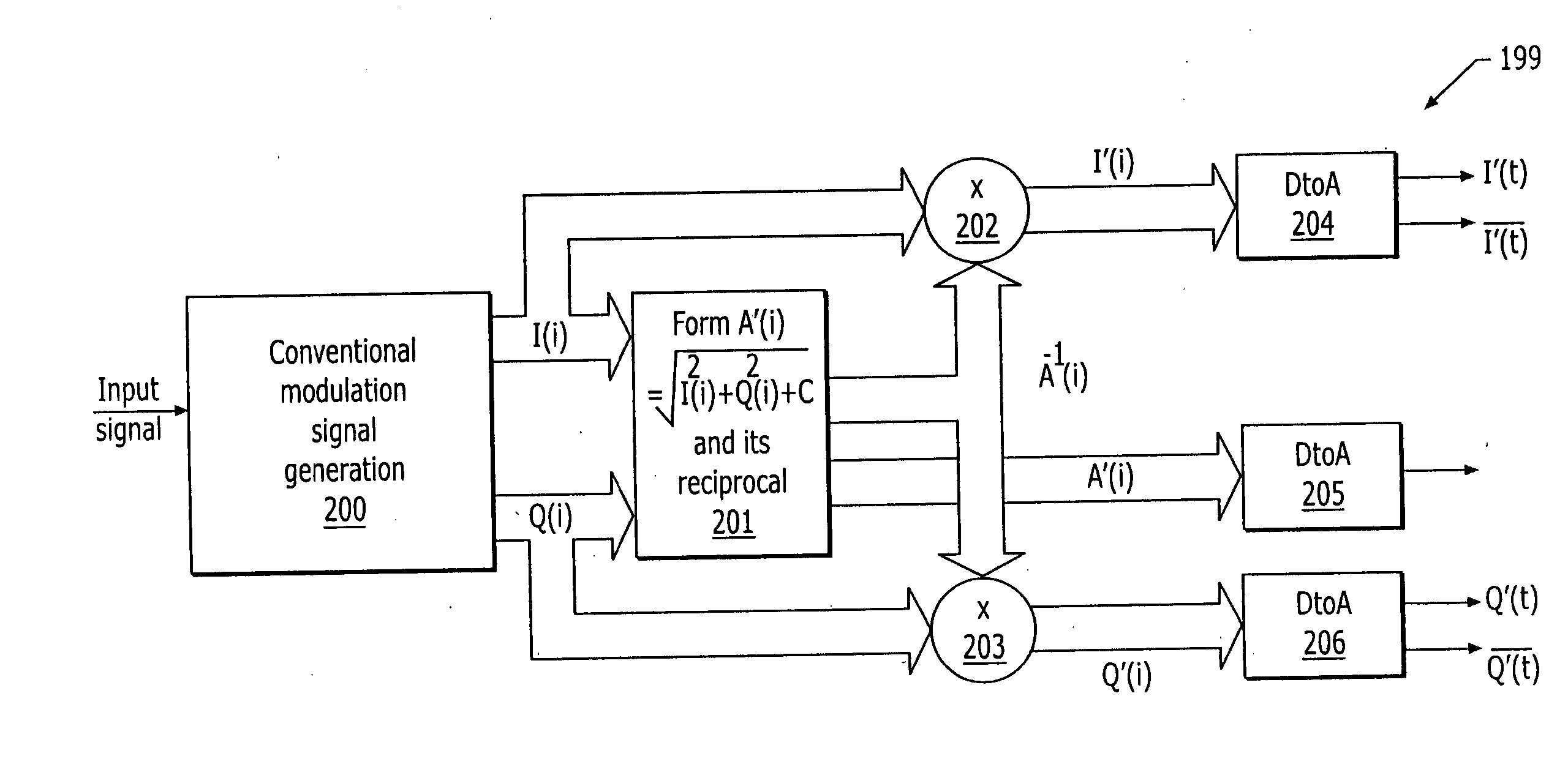
Pseudo-polar modulation for radio transmitters
a radio transmitter and pseudo-polar technology, applied in the field of wireless communication transmitters, can solve the problems of linear amplifiers still producing distortion, signal modulation in phase alone is not perfectly bandlimited, and distortion form, so as to reduce the effect of amplitud
- Summary
- Abstract
- Description
- Claims
- Application Information
AI Technical Summary
Benefits of technology
Problems solved by technology
Method used
Image

Examples
Embodiment Construction
The present invention now will be described more fully hereinafter with reference to the accompanying drawings, in which embodiments of the invention are shown. However, this invention should not be construed as limited to the embodiments set forth herein. Rather, these embodiments are provided so that this disclosure will be thorough and complete, and will fully convey the scope of the invention to those skilled in the art. Like numbers refer to like elements throughout.
It also will be understood that, as used herein, the term “comprising” or “comprises” is open-ended, and includes one or more stated elements, steps and / or functions without precluding one or more unstated elements, steps and / or functions.
The present invention is described below with reference to block diagrams and / or operational illustrations of methods and wireless receivers according to embodiments of the invention. It is understood that each block of the block diagrams and / or operational illustrations, and ...
PUM
 Abstract
Description
Claims
Application Information