Miniaturizable electromagnetic relay

a technology of electromagnetic relays and relays, applied in the field of electromagnetic relays, can solve the problems of reducing the size of electromagnetic relays, affecting the performance of current carrying, and limiting the sectional area of electromagnetic relays, and achieves excellent current carrying performance and interruption performance, and small siz

Active Publication Date: 2005-03-03
EM DEVICES CORP
View PDF1 Cites 21 Cited by
  • Summary
  • Abstract
  • Description
  • Claims
  • Application Information

AI Technical Summary

Benefits of technology

[0008] It is therefore an object of this invention to provide a three-phase control electromagnetic r

Problems solved by technology

This goes against customers' requests for saving as much space as possible.
However, inasmuch as the fixed contact terminal has the plate-like shape, it can not be efficiently arranged on a base, which precludes reduction in size of the electromagnetic relay.
Moreover, in order to decrease a conductor resistance value from the movable contact to the extraction t

Method used


Image

  • Miniaturizable electromagnetic relay
  • Miniaturizable electromagnetic relay
  • Miniaturizable electromagnetic relay

Examples


Embodiment Construction

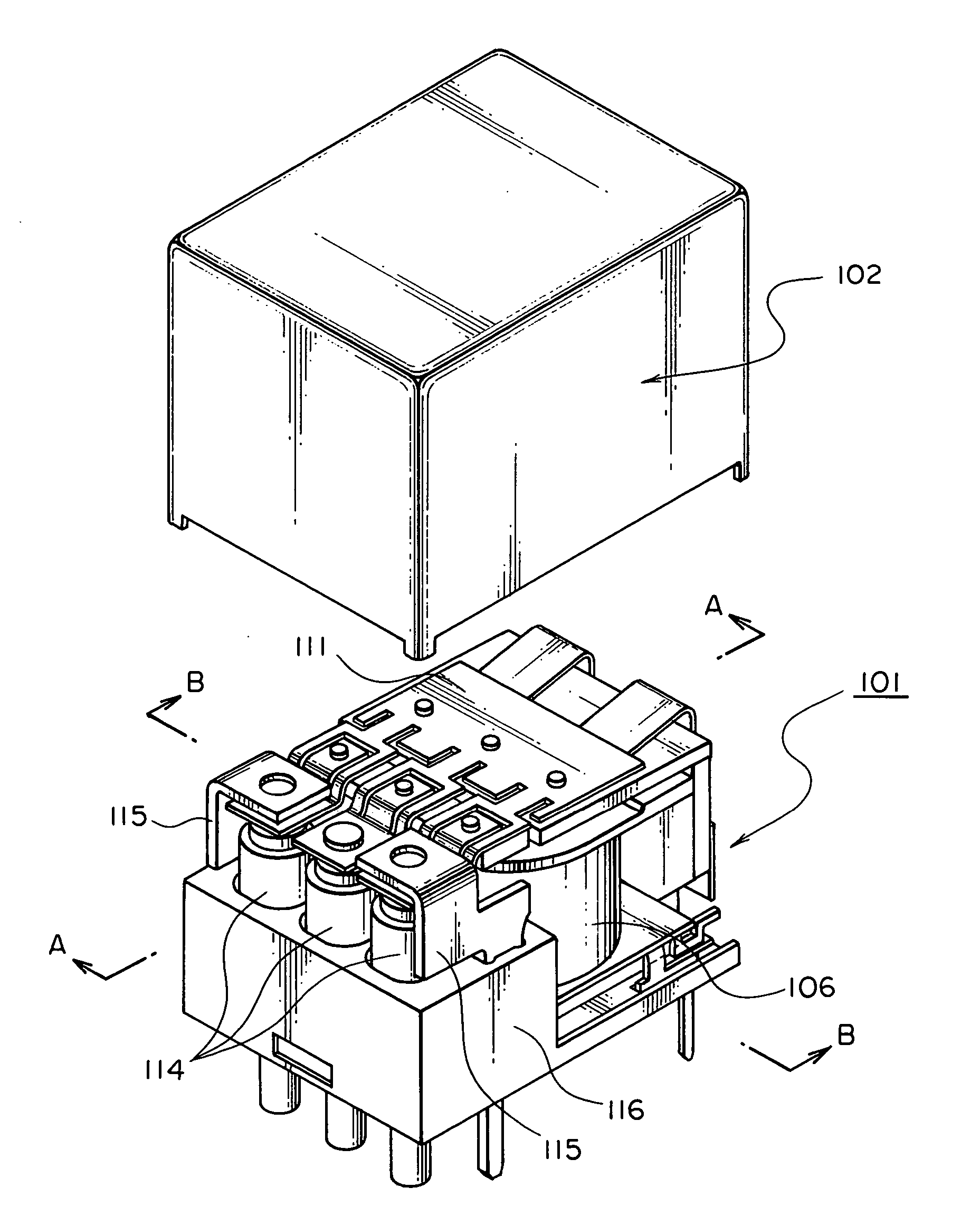
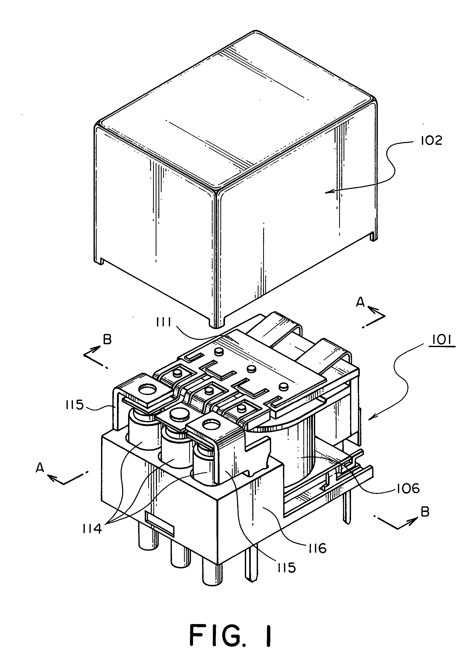
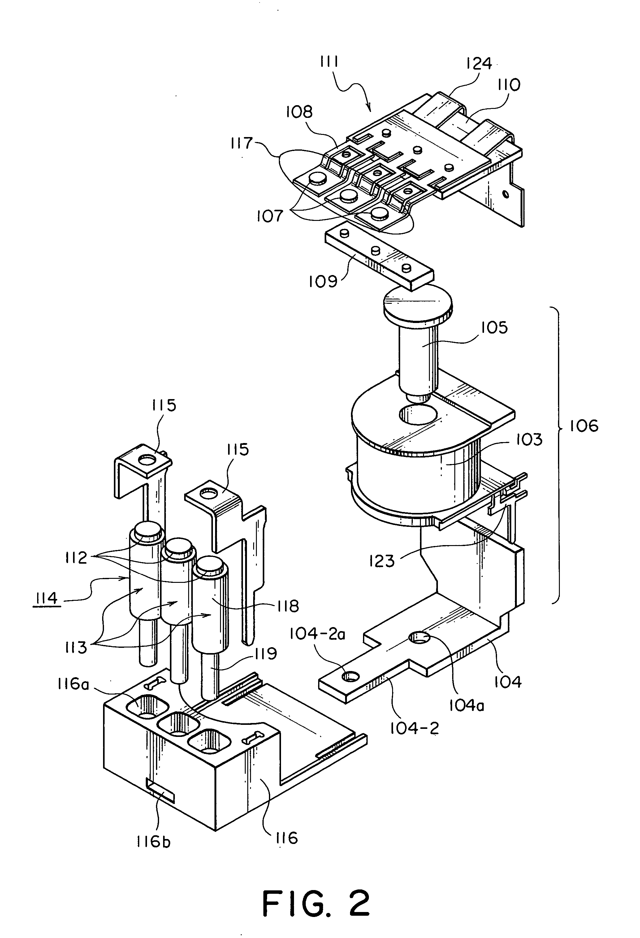
[0020] Referring to FIGS. 1 to 5, description will be made of an electromagnetic relay according to a preferred embodiment of this invention. FIG. 1 is a perspective view of the electromagnetic relay, and FIG. 2 is an exploded perspective view of the electromagnetic relay illustrated in FIG. 1.

[0021] In FIG. 1, the electromagnetic relay in this embodiment comprises an electromagnetic relay body 101 and a cover 102 for covering it. The electromagnetic relay body 101 comprises a magnet assembly 106, a movable contact spring assembly 111, three fixed contact terminal assemblies 114, two backstop terminals 115, and a resin base 116 for mounting the foregoing respective components thereon.

[0022] In FIG. 2, the magnet assembly 106 comprises a coil assembly 103, a substantially L-shaped yoke 104, a core 105, and two coil terminals 123 (only one is illustrated) attached to the coil assembly 103. The movable contact spring assembly 111 comprises a movable spring 108, three movable contacts...


PUM


Abstract

An electromagnetic relay has three fixed contact terminal assemblies arrayed in a row at regular intervals, and a movable contact spring assembly having three movable contacts. An armature is caused to swing by turning on and off an exciting current to a coil assembly so that normally-open contact portions are closed and opened. A movable spring of the movable contact spring assembly is branched into three portions on one end side thereof and a substantially U-shaped slit is formed in each of the branched portions so that spring flexible portions and a current-carrying path portion are separately formed in each branched portion. A current-carrying plate is joined to the three current-carrying path portions so that the three movable contacts are electrically connected together.

Description

[0001] This application claims priority to prior Japanese patent application JP 2003-303801, the disclosure of which is incorporated herein by reference. BACKGROUND OF THE INVENTION [0002] This invention relates to an electromagnetic relay and, in particular, relates to an electromagnetic relay suitable for controlling a three-phase motor adapted to be mounted on an automobile. [0003] In recent years, automotive power steering has been shifting from the hydraulic type to the electric type for the purpose of improvement in fuel consumption. Most electric power steering systems are of a DC motor driven type, but those of a three-phase motor driven type have been increasing following the application thereof to large-displacement vehicles. In case of the electric power steering system driven by the three-phase motor, a switch is required for simultaneously controlling the three phases. For example, an electromagnetic relay is useful which simultaneously controls the three phases at the ...

Claims


Application Information

Patent Timeline
IPC IPC(8): H01H50/24H01H50/00H01H50/14H01H50/28H01H50/56H01H50/60H01H51/06
CPCH01H50/002H01H50/60H01H50/28H01H50/14
Inventor CHIDA, YOSHIFUMICHIBA, KEI
Owner EM DEVICES CORP
Why Eureka
Try Eureka