Projection apparatus, projection method and recording medium recording the projection method

a projection apparatus and projection method technology, applied in the direction of pulse technique, printer, camera focusing arrangement, etc., can solve the problems of large projector size, complicated operation, and inability to calculate (or compute) the operations described abov

Active Publication Date: 2005-03-03
CASIO COMPUTER CO LTD
View PDF8 Cites 90 Cited by
  • Summary
  • Abstract
  • Description
  • Claims
  • Application Information

AI Technical Summary

Problems solved by technology

KOKAI Publication No. 2000-241874 However, the portable type projector disclosed in the forgoing Patent document 1 has the problems described below.
As a result, time becomes inevitably long to calculate (or compute) the operations described above.
As a result, the whole of the projector is made into a large size, and becomes complicate.

Method used


Image

  • Projection apparatus, projection method and recording medium recording the projection method
  • Projection apparatus, projection method and recording medium recording the projection method
  • Projection apparatus, projection method and recording medium recording the projection method

Examples


first embodiment

[0024] (First Embodiment)

[0025] The first embodiment will be described below with reference to the accompanying drawings. Here, the present invention is applied to a projector.

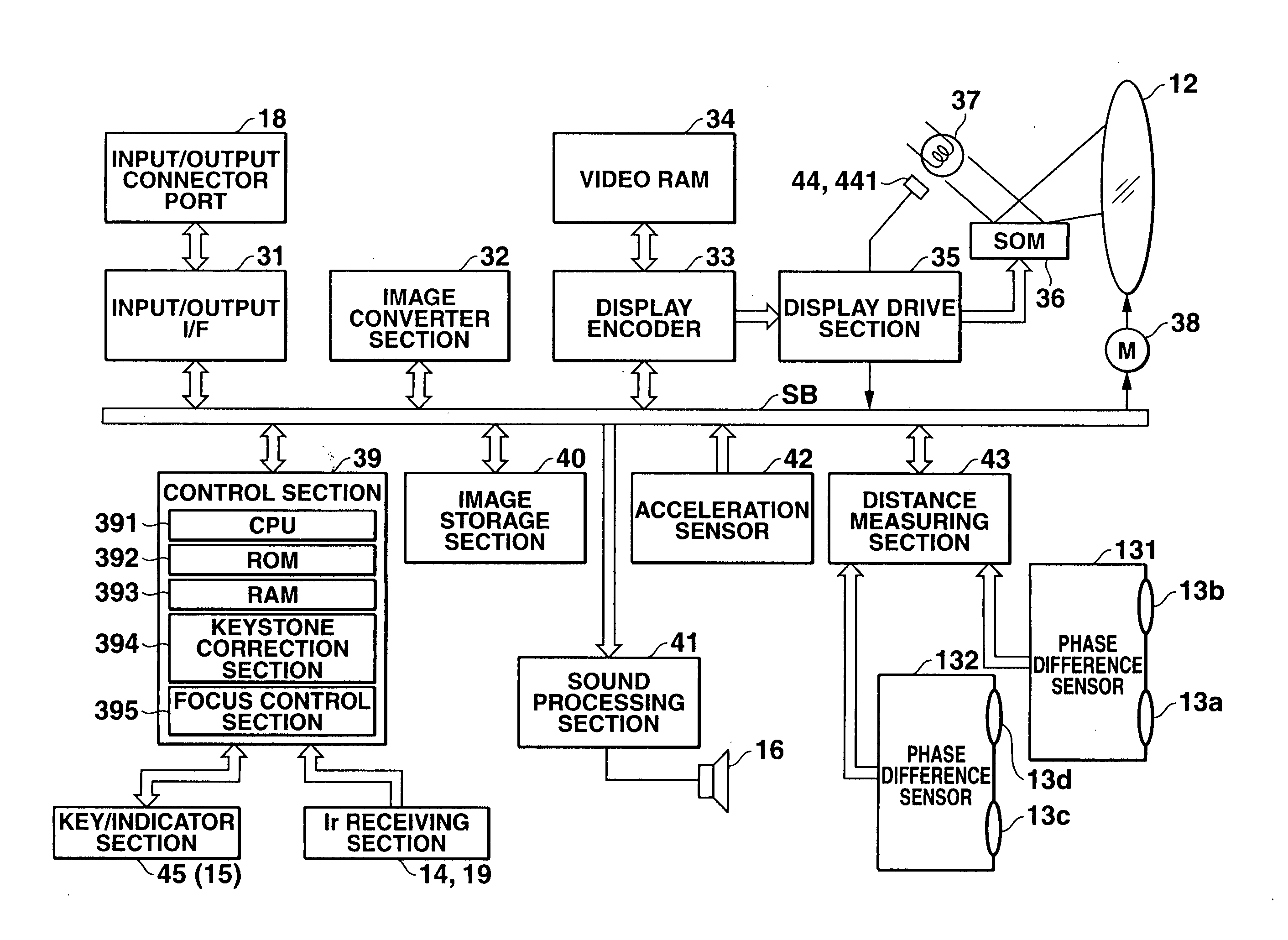
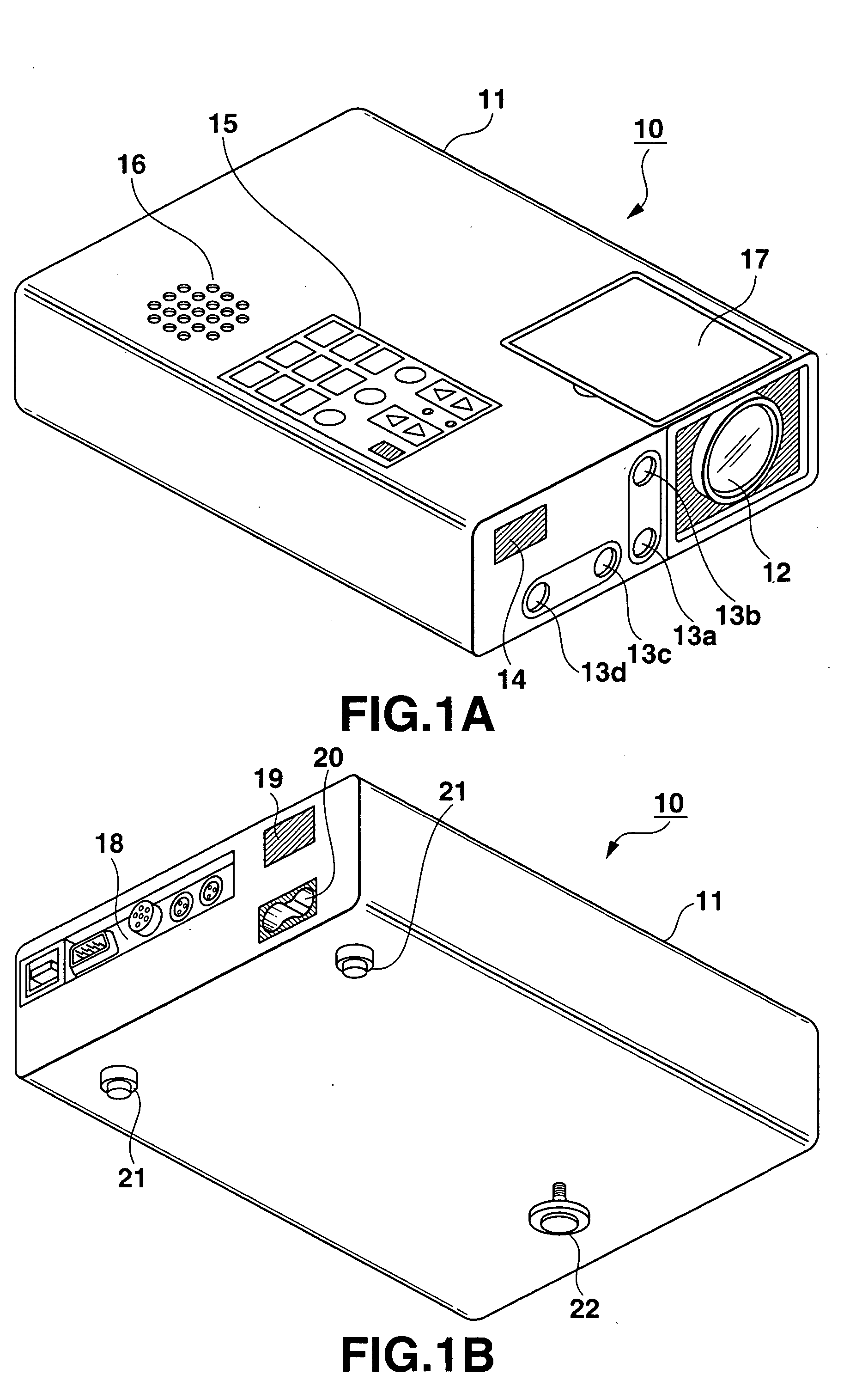
[0026]FIG. 1 shows the appearance of a projector 10 according to the first embodiment. As shown in FIG. 1A, a rectangular casing 11 is provided with projection lens 12, two pairs of focusing lenses 13a, 13b and 13c, 13d, and Ir (infrared) receiving section 14 at the front side.

[0027] The projection lens 12 is used for projecting an optical image formed by special optical modulator element such as micro-mirror element described later. Here, the projection lens 12 is capable of arbitrarily varying focal position and zoom position (projection angle).

[0028] The focusing lenses 13a to 14d function as part of a phase difference sensor 13. The focusing lenses measure a distance to the subject from their parallax with respect to a subject image based on the principle of triangulation, that is, to the projection ima...

second embodiment

[0090] (Second Embodiment)

[0091] The second embodiment will be described below with reference to the accompanying drawings. Here, the present invention is applied to a projector.

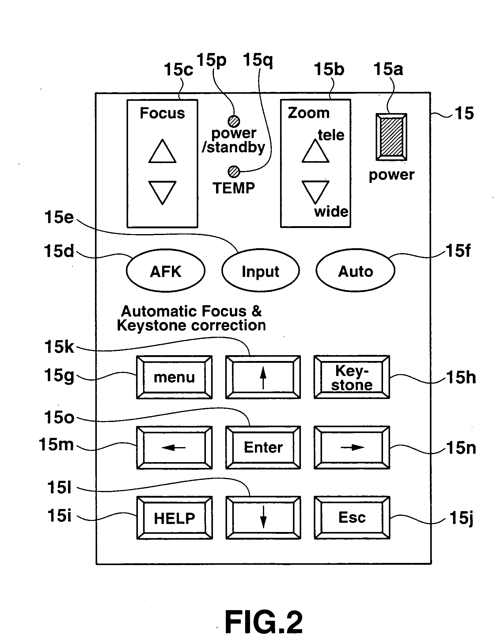
[0092] The projector 10 according to the second embodiment is basically the same as shown in FIG. 1 to FIG. 3. More specifically, the appearance of the projector 10 is the same as FIG. 1. The arrangement and configuration of the main key / indicator 15 provided on the casing 11 of the projector 10 is the same as FIG. 2. The functional configuration of electronic circuits is the same as FIG. 3. The same reference numerals are used to designate parts identical to above, and the illustration and explanation are omitted.

[0093] The operation of the second embodiment will be described below.

[0094]FIG. 7 is a flowchart showing the procedure of automatic focus and keystone correction. The procedure is taken as initial setting, which is carried out after a power-on state is given by operating the “power” key 15a on ...


PUM


Abstract

A projection apparatus comprising a projection section for projecting an image corresponding to an input image signal, a distance measuring section for measuring each distance of several positions on an image projection plane made by the projection section, a focus control section for making keystone correction on an image projected by the projection section so that a projection image is formed into a rectangular shape having a proper aspect ratio based on each distance obtained by the distance measuring section while controlling a focus position of the image projected by the projection section, and a control section for instructing to carry out processing by the focus control section.

Description

CROSS-REFERENCE TO RELATED APPLICATIONS [0001] This application is based upon and claims the benefit of priority from prior Japanese Patent Application No. 2003-299887, filed Aug. 25, 2003, the entire contents of which are incorporated herein by reference. BACKGROUND OF THE INVENTION [0002] 1. Field of the Invention [0003] The present invention relates to an automatic projection apparatus having an automatic focusing function, a projection method, and a recording medium recording the projection method. [0004] 2. Description of the Related Art [0005] Conventionally, a portable type projector has been disclosed in the following Patent Document 1, for example. The projector is provided with a monitor camera to monitor a projection screen, and thereby, automatically carrying out various controls required for image display. [0006] [Patent Document 1]: [0007] JPN. PAT. APPLN. KOKAI Publication No. 2000-241874 However, the portable type projector disclosed in the forgoing Patent document 1...

Claims


Application Information

Patent Timeline
Patent Type & Authority Applications(United States)
IPC IPC(8): G02B7/28G03B21/00H04N5/74H04N9/31H04N17/00
CPCH04N5/74H04N9/3197H04N9/3194
Inventor AKUTSU, TAKASHI
Owner CASIO COMPUTER CO LTD
Why Eureka
Try Eureka