
Spatial-heterodyne interferometry for reflection and transmission (SHIRT) measurements

a technology of spatial heterodyne and interferometry, which is applied in the field of spatial heterodyne interferometry for reflection and transmission measurements, and can solve the problems of long scans, no complex wavefront information, and no information regarding the interior of an object of interest provided by ddh

Inactive Publication Date: 2005-03-03
UT BATTELLE LLC
View PDF27 Cites 34 Cited by
  • Summary
  • Abstract
  • Description
  • Claims
  • Application Information

AI Technical Summary

Benefits of technology

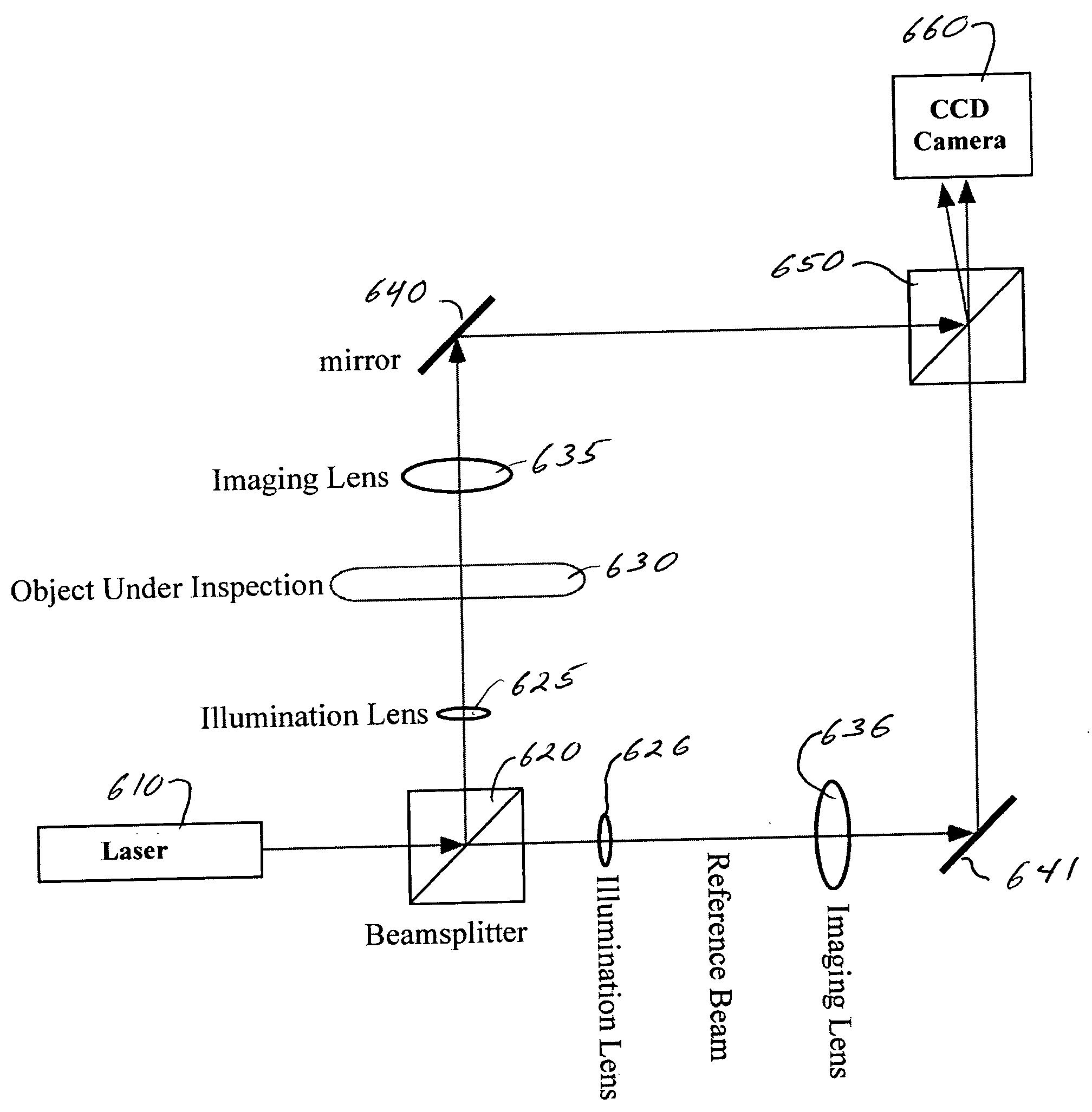
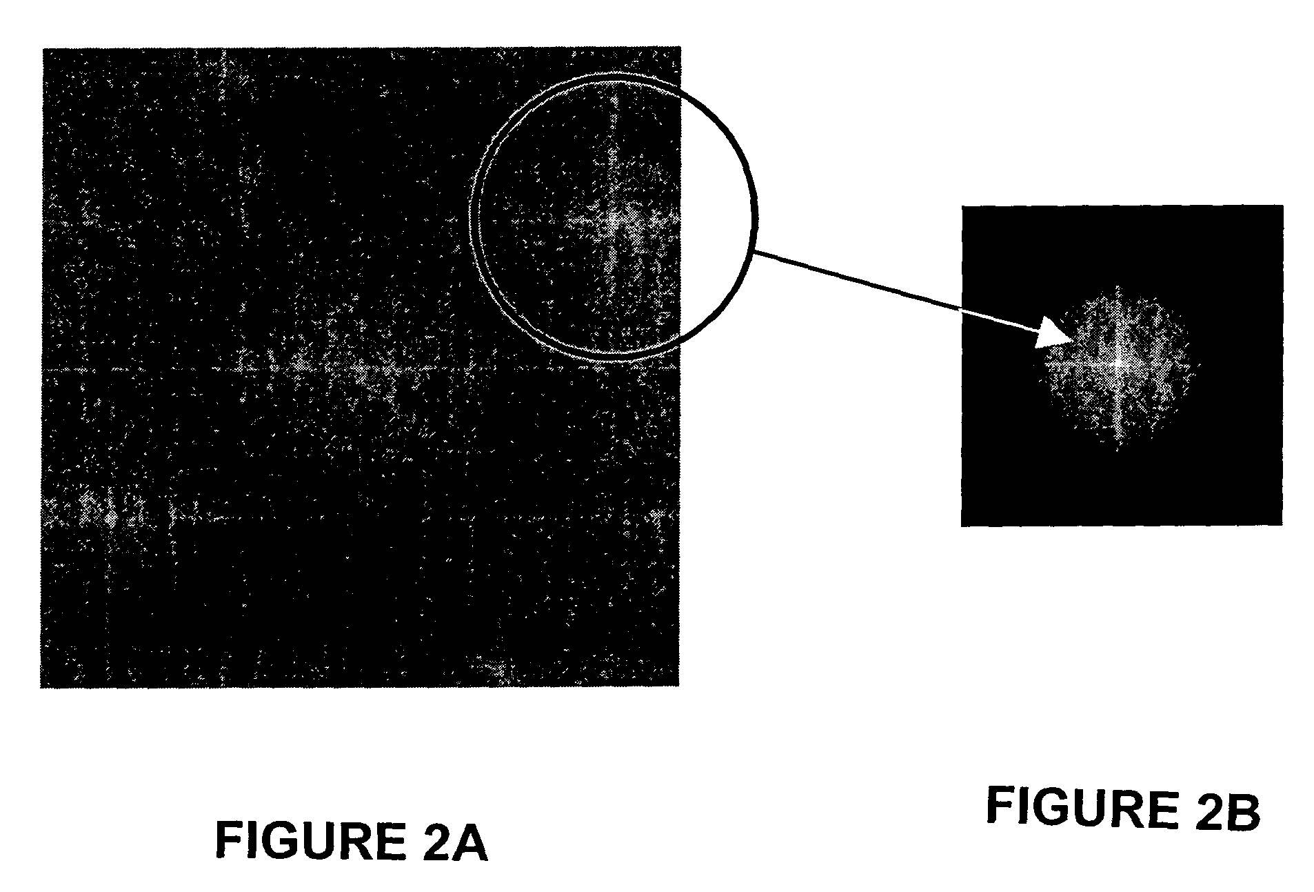
According to an aspect of the invention, a process comprises: digitally recording a spatially-heterodyned hologram including spatial heterodyne fringes for Fourier analysis using a reference beam and an object beam; Fourier analyzing the digitally recorded spatially-heterodyned hologram, by shifting an original origin of the digitally recorded spatially-heterodyned hologram to sit on top of a spatial-heterodyne carrier frequency defined by an angle between the reference beam and the object beam, to define an analyzed image; digitally filtering the analyzed image to cut off signals around the original origin to define a result; and performing an inverse Fourier transform on the result, wherein the object beam is transmitted through an object that is at least partially translucent. According to another aspect of the invention, a machine comprises: a source of coherent light energy; a reference beam subassembly optically coupled to the source of coherent light; an object beam subassembly optically coupled to the source of coherent light; a beamsplitter optically coupled to both the reference beam subassembly and the object beam subassembly; and a pixilated detection device optically coupled to the beamsplitter, wherein the object beam subassembly includes an object that is at least partially translucent, the object transmissively optically coupled between the source of coherent light energy and the beamsplitter.
According to another aspect of the invention, a process comprises: digitally recording a first spatially-heterodyned hologram including spatial heterodyne fringes for Fourier analysis using a first reference beam and a first object beam; digitally recording a second spatially-heterodyned hologram including spatial heterodyne fringes for Fourier analysis using a second reference beam and a second object beam; Fourier analyzing the digitally recorded first spatially-heterodyned hologram, by shifting a first original origin of the digitally recorded first spatially-heterodyned hologram to sit on top of a first spatial-heterodyne carrier frequency defined by a first angle between the first reference beam and the first object beam, to define a first analyzed image; Fourier analyzing the digitally recorded second spatially-heterodyned hologram, by shifting a second original origin of the digitally recorded second spatially-heterodyned hologram to sit on top of a second spatial-heterodyne carrier frequency defined by a second angle between the second reference beam and the second object beam, to define a second analyzed image; digitally filtering the first analyzed image to cut off signals around the first original origin to define a first result; and digitally filtering the second analyzed image to cut off signals around the second original origin to define a second result; performing a first inverse Fourier transform on the first result, and performing a second inverse Fourier transform on the second result, wherein the first object beam is transmitted through an object that is at least partially translucent and the second object beam is reflected from the object. According to another aspect of the invention, a machine comprises: a source of coherent light energy; a transmission reference beam subassembly optically coupled to the source of coherent light; a reflection reference beam subassembly optically coupled to the source of coherent light; an object beam subassembly optically coupled to the source of coherent light, the object beam subassembly including a transmission object beam path and a reflection object beam path; a transmission beamsplitter optically coupled to both the transmission reference beam subassembly and the object beam subassembly; a reflection beamsplitter optically coupled to both the reflection reference beam subassembly and the object beam subassembly; and a pixilated detection device optically coupled to at least one member selected from the group consisting of the transmission beamsplitter and the reflection beamsplitter, wherein the object beam subassembly includes an object that is at least partially translucent, the object i) transmissively optically coupled between the source of coherent light energy and the transmission beamsplitter and ii) reflectively optically coupled between the source of coherent light energy and the reflection beamsplitter.

Problems solved by technology

This reflected wave is combined with a reference wave at the digital imaging device so that they interfere and create a set of linear interference fringes.
However, DDH does not provide information regarding the interior of an object of interest and only provides information regarding the surface of the object.
However, a limitation of PCM is that no complex wavefront information is provided, the phase information from PCM being represented by amplitude only.
While this technique is able to measure phase changes, 30 seconds are required for each height measurement and, therefore, a slow scan would be required to measure phase changes across an interior portion of an object and a very long scan would be required to measure phase changes over an entire mask.
Heretofore, the requirements of both providing complex wavefront information regarding an interior portion of an object and providing that information quickly have not been met.

Method used


Image

  • Spatial-heterodyne interferometry for reflection and transmission (SHIRT) measurements
  • Spatial-heterodyne interferometry for reflection and transmission (SHIRT) measurements
  • Spatial-heterodyne interferometry for reflection and transmission (SHIRT) measurements

Examples


examples

Specific embodiments of the invention will now be further described by the following, nonlimiting examples which will serve to illustrate in some detail various features. The following examples are included to facilitate an understanding of ways in which the invention may be practiced. It should be appreciated that the examples which follow represent embodiments discovered to function well in the practice of the invention, and thus can be considered to constitute preferred modes for the practice of the invention. However, it should be appreciated that many changes can be made in the exemplary embodiments which are disclosed while still obtaining like or similar result without departing from the spirit and scope of the invention. Accordingly, the examples should not be construed as limiting the scope of the invention.

Example Set 1

The invention can include a method for measuring (in a single high-speed digital image capture) the complex wavefront of an electromagnetic wave after it...


PUM

PropertyMeasurementUnit
spatial-heterodyne carrier frequencyaaaaaaaaaa
angleaaaaaaaaaa
thicknessaaaaaaaaaa

Abstract

Systems and methods are described for spatial-heterodyne interferometry for reflection and transmission (SHIRT) measurements. A method includes digitally recording a first spatially-heterodyned hologram using a first reference beam and a first object beam; digitally recording a second spatially-heterodyned hologram using a second reference beam and a second object beam; Fourier analyzing the digitally recorded first spatially-heterodyned hologram to define a first analyzed image; Fourier analyzing the digitally recorded second spatially-heterodyned hologram to define a second analyzed image; digitally filtering the first analyzed image to define a first result; and digitally filtering the second analyzed image to define a second result; performing a first inverse Fourier transform on the first result, and performing a second inverse Fourier transform on the second result. The first object beam is transmitted through an object that is at least partially translucent, and the second object beam is reflected from the object.

Description

BACKGROUND OF THE INVENTION 1. Field of the Invention The invention relates generally to the field of spatial-heterodyne interferometry (SHI). More particularly, the invention relates to methods and machinery for obtaining spatial-heterodyne interferometry for transmission (SHIFT) and spatial-heterodyne interferometry for reflection and transmission (SHIRT) measurements. 2. Discussion of the Related Art U.S. Pat. Nos. 6,078,392 and 6,525,821 relate to Direct-to-Digital Holography (DDH). In DDH, a reflected object wavefront is combined with a reference wavefront at a small angle on the surface of a digital imaging device. The small angle generates a set of linear fringes that spatially heterodynes the reflected object wavefront. Fourier analysis is then used to isolate the image at the heterodyne frequency and reconstruct the complex wavefront, Voelkl (1999). DDH is an implementation of spatial-heterodyne interferometry with Fourier reconstruction to capture complex wavefronts r...

Claims


Application Information

Patent Timeline
Patent Type & Authority Applications(United States)
IPC IPC(8): G01B11/06G03F1/00G03H1/08
CPCG01B11/0675G03F1/84G03H1/0866G03H2210/12G03H2001/0469G03H2001/0471G03H2001/0456
Inventor HANSON, GREGORY R.BINGHAM, PHILIP R.TOBIN, KEN W.
Owner UT BATTELLE LLC
Learn More