Image processing apparatus for receiving a request relating to image processing from an external source and executing the received request

a technology of image processing and external sources, applied in the direction of digital computers, instruments, digital output to print units, etc., can solve the problems of time-consuming work, inability to easily meet requests, and inability to configure mfp to meet requests. easy, the effect of extension

Active Publication Date: 2005-03-03
KONICA MINOLTA INC
View PDF4 Cites 112 Cited by
  • Summary
  • Abstract
  • Description
  • Claims
  • Application Information

AI Technical Summary

Benefits of technology

[0009] The present invention is made in view of the problems noted above, and has an object to provide an image processing apparatus which allows easy extension of the functionality with substantially no alterations to existing applications.
[0011] With the configuration stated above, the image processing apparatus is provided with the second control program. Consequently, even after the image processing apparatus is delivered to a user, it is possible to extend the functionality of the image processing apparatus without altering the existing application program, so that additional functionality that the existing application is incapable of can be performed from an external source through the second application program. In short, the image processing apparatus is of improved scalability and improved user convenience.

Problems solved by technology

Naturally, it takes enormous amounts of time to provide all the software programs individually.
Although efficiency in development is realized, the above technique has a following problem.
Unfortunately, however, the MFP is not configured to meet the request easily.
For example, when the user desires scanning to be performed in a mode not provided by an existing scan application, the existing application must be altered on the whole exclusively for that particular user, which requires time-consuming work and thus is not practical.
As above, MFPs according to the conventional technique are extremely poor in the scalability of functionality.

Method used


Image

  • Image processing apparatus for receiving a request relating to image processing from an external source and executing the received request
  • Image processing apparatus for receiving a request relating to image processing from an external source and executing the received request
  • Image processing apparatus for receiving a request relating to image processing from an external source and executing the received request

Examples


first embodiment

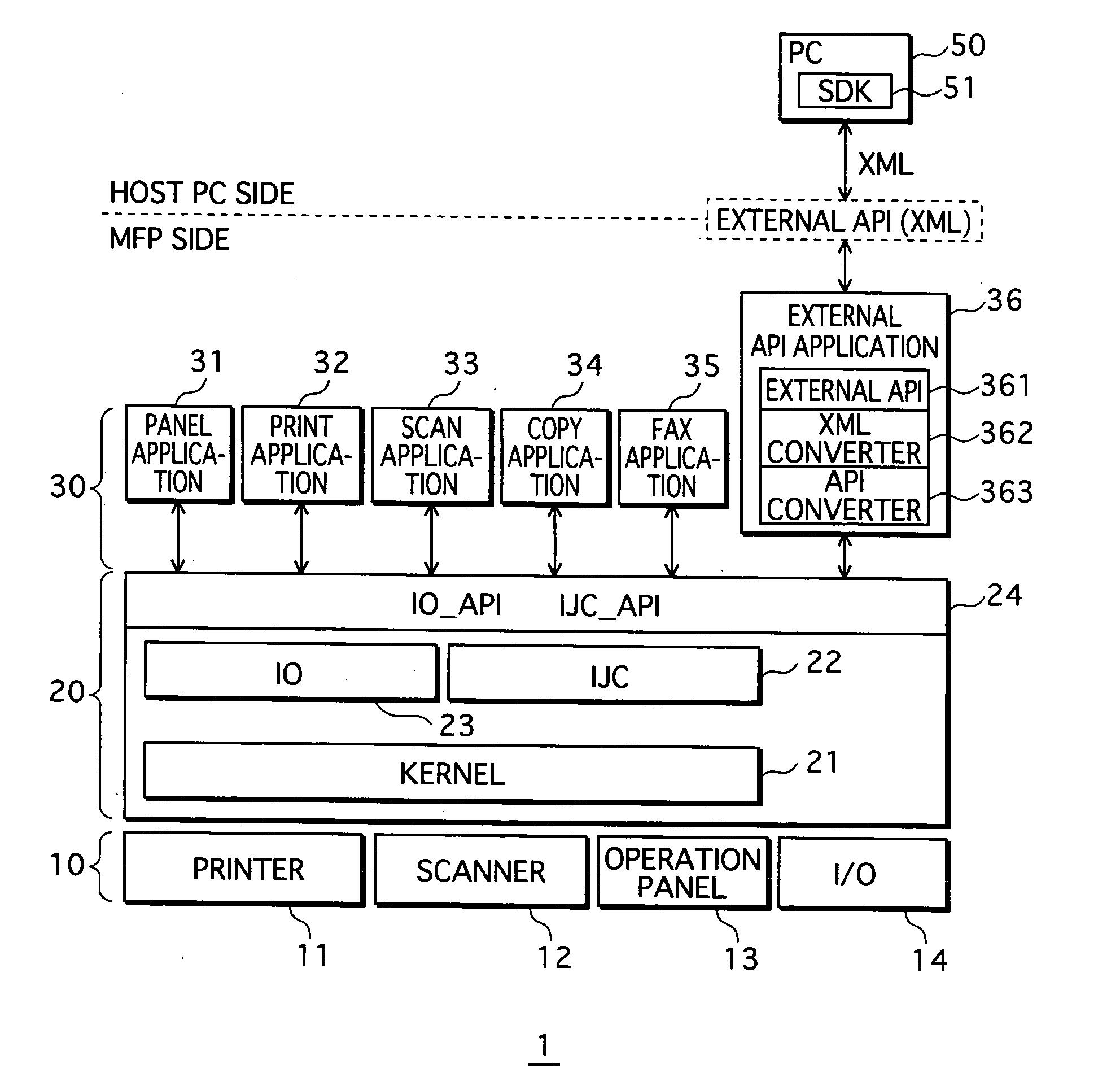
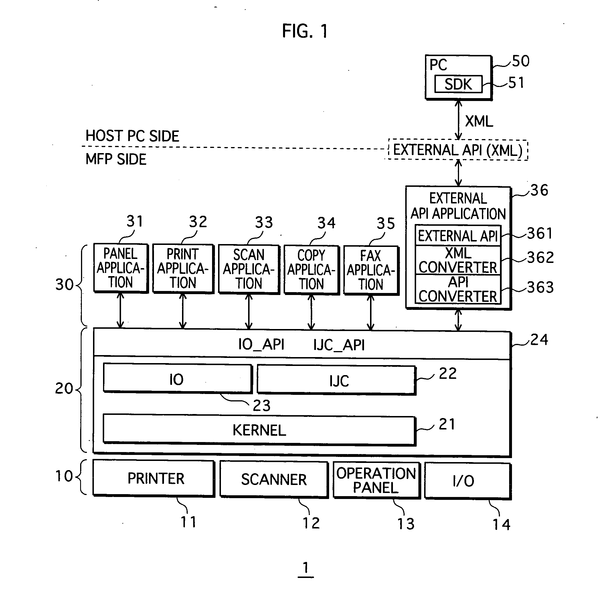
[0030]FIG. 1 is a view illustrating a system configuration of an MFP 1 according to a first embodiment of the present invention.

[0031] As illustrated in the figure, an MFP 1 has a hierarchical architecture with a device layer (hardware resource) 10 as the bottommost layer, a control layer 20 directly controlling the device layer 10, and an application layer 30 as the topmost layer. The MFP 1 is a digital multifunction peripheral capable of a plurality of jobs relating to image processing, including the above-described scan job, copy job, print job, and FAX job. Further, the MFP 1 is connected to a personal computer (hereinafter, “PC”) 50 via a network (not illustrated) such as a LAN, and mutually receive and transmit various data using, for example, TCP / IP (Transmission Control Protocol / Internet Protocol).

[0032] The device layer 10 includes a printer 11 acting as an image forming unit, a scanner 12 acting as a read unit, an operation panel 13 acting as a display unit, and an I / O u...

second embodiment

[0090] According to the first embodiment described above, the second control program (external API application) is arranged on the same layer as the applications 31-35. Second embodiment differs from the first embodiment in that a control layer, an external API unit, and an application layer are arranged in a hierarchal architecture in the stated order. For the convenience sake, the same reference numerals are used for similar or identical components and thus are not described. The same also holds in a third embodiment, which will be later described.

[0091]FIG. 6 is a view illustrating a system configuration of an MFP 100 according to the second embodiment.

[0092] As illustrated in the figure, the MFP 100 has a hierarchical architecture with a device layer (hardware resource) 10 as the bottommost layer, a control layer (first control program)120 for directly controlling the device layer 10, an external API unit (second control program) 130 over the control layer 120, and an applicat...

third embodiment

[0130] According to the second embodiment described above, the hardware resource 10, the control layer 120, the external API unit 130, and the application layer 140 are arranged in a hierarchical architecture in the stated order. A third embodiment differs from the second embodiment in that a control layer is arranged between a hardware resource and an application layer and an external API unit is arranged superordinate to the application layer in a hierarchical architecture. The control layer is capable of giving and receiving commands to and from both the application layer and the external API unit. Further, the external API unit is capable of giving and receiving commands to and from the application layer.

[0131]FIG. 10 is a view illustrating a system configuration of an MFP 200 according to the third embodiment.

[0132] As illustrated in the figure, the MFP 200 has a hierarchical architecture with a device layer (hardware resource) 10 as the bottommost layer, a control layer 220 ...


PUM


Abstract

Disclosed is an image processing apparatus composed in a hierarchical architecture of a hardware resource, a first control program over the hardware resource, a second control program and an application program over the first control program. The first control program includes a first API for receiving a first request relating to image processing from the second control program and a second request relating to image processing from the application program, and controls, on receiving either of the first and second requests, the hardware resource to perform image processing based on the received request. The second control program includes a second API publicly released in advance for receiving a third request relating to image processing from an external source, converts the received third request to a command supported by the first API, and passes the command as the first request to the first control program.

Description

[0001] This application is based on applications Nos. 2003-309293, 2003-309294, and 2003-309295 filed in Japan, the contents of which are hereby incorporated by reference. BACKGROUND OF THE INVENTION [0002] (1) Field of the Invention [0003] The present invention relates to an image processing apparatus for receiving a request relating to image processing from an external source and executing the received request. [0004] (2) Description of the Related Art [0005] Recently, so-called digital multifunction peripherals (hereinafter, “MFPs”) are in wide use in an office environment as well as in other environments. MFPs are peripherals having multifunction including: a scan job of scanning an image of a document; a copy job of printing out scanned image data of a document; a print job of printing out image data according to a print instruction given from an external terminal; and a FAX job of transmitting / receiving image data to / from an external FAX device. [0006] Being capable of perform...

Claims


Application Information

Patent Timeline
Patent Type & Authority Applications(United States)
IPC IPC(8): G06F3/00G06F9/44G06F15/00H04N1/00H04N1/32
CPCH04N1/00204H04N1/00954H04N1/32561H04N2201/0094H04N2201/0046H04N2201/0074H04N2201/0024
Inventor SHIBATA, KOICHIMURAKAMI, MASAKAZU
Owner KONICA MINOLTA INC
Why Eureka
Try Eureka