Laminated solid electrolytic capacitor and laminated transmission line device increased in element laminating number without deterioration of elements
a solid electrolytic capacitor and laminated technology, applied in the direction of variable capacitors, fixed capacitors, fixed capacitor details, etc., can solve the problems of deterioration of oxidized film as a dielectric layer formed between the anode body and the cathode body, and damage to solid electrolytic capacitor elements, so as to achieve the effect of increasing capacity, reducing size, and reducing the number of elements
- Summary
- Abstract
- Description
- Claims
- Application Information
AI Technical Summary
Benefits of technology
Problems solved by technology
Method used
Image

Examples
first embodiment
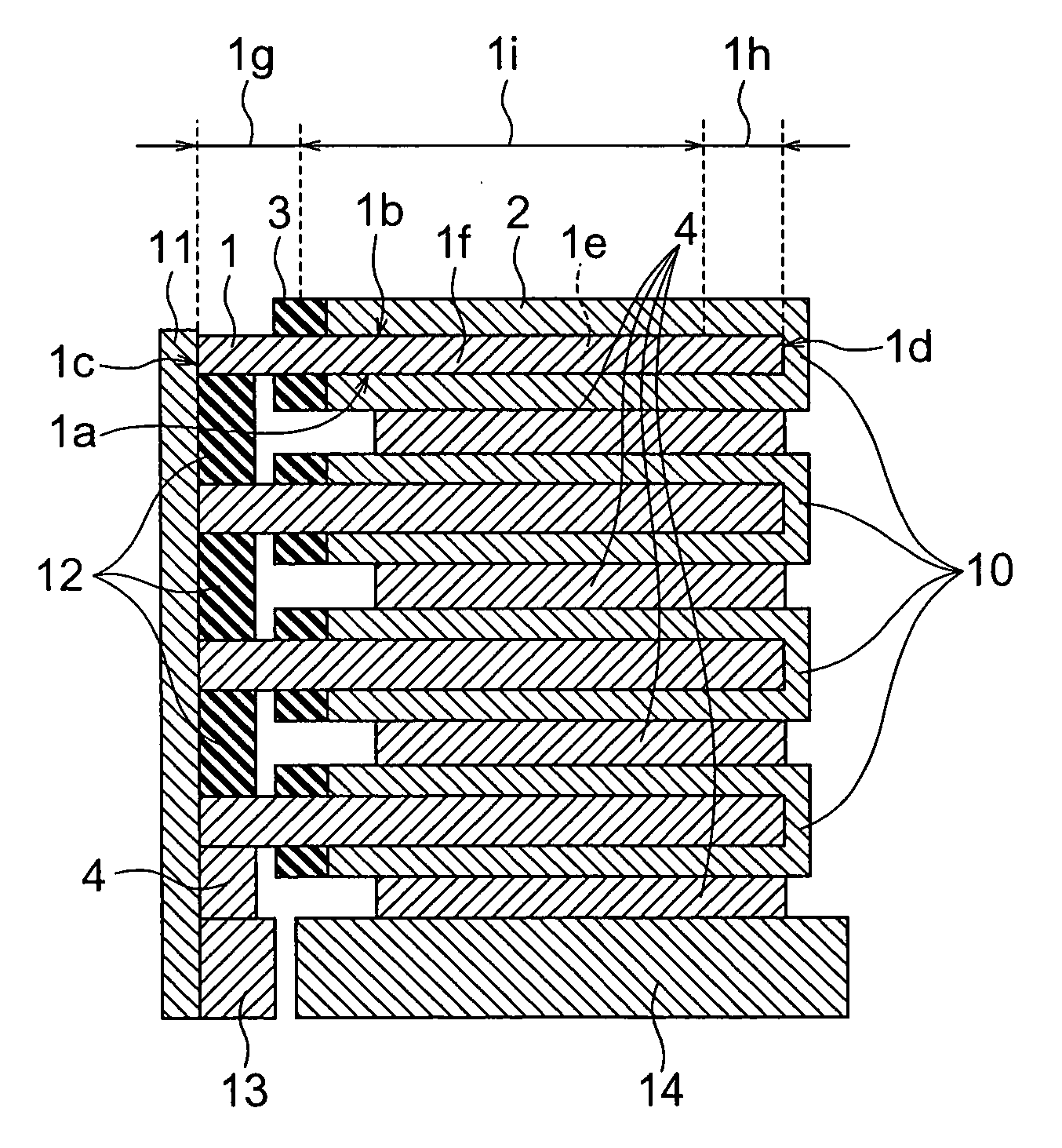
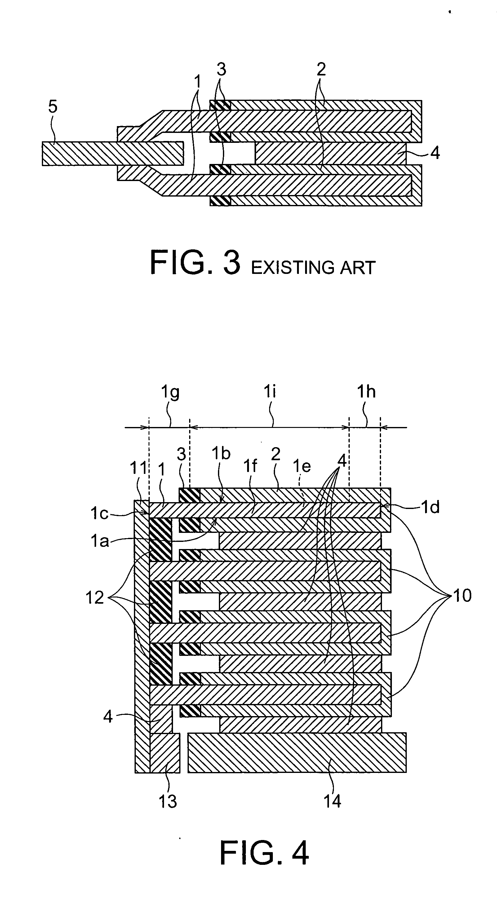
[0058] Referring to FIG. 4, in a laminated solid electrolytic capacitor according of a first embodiment of this invention, four solid electrolytic capacitor elements 10 are laminated to one another.
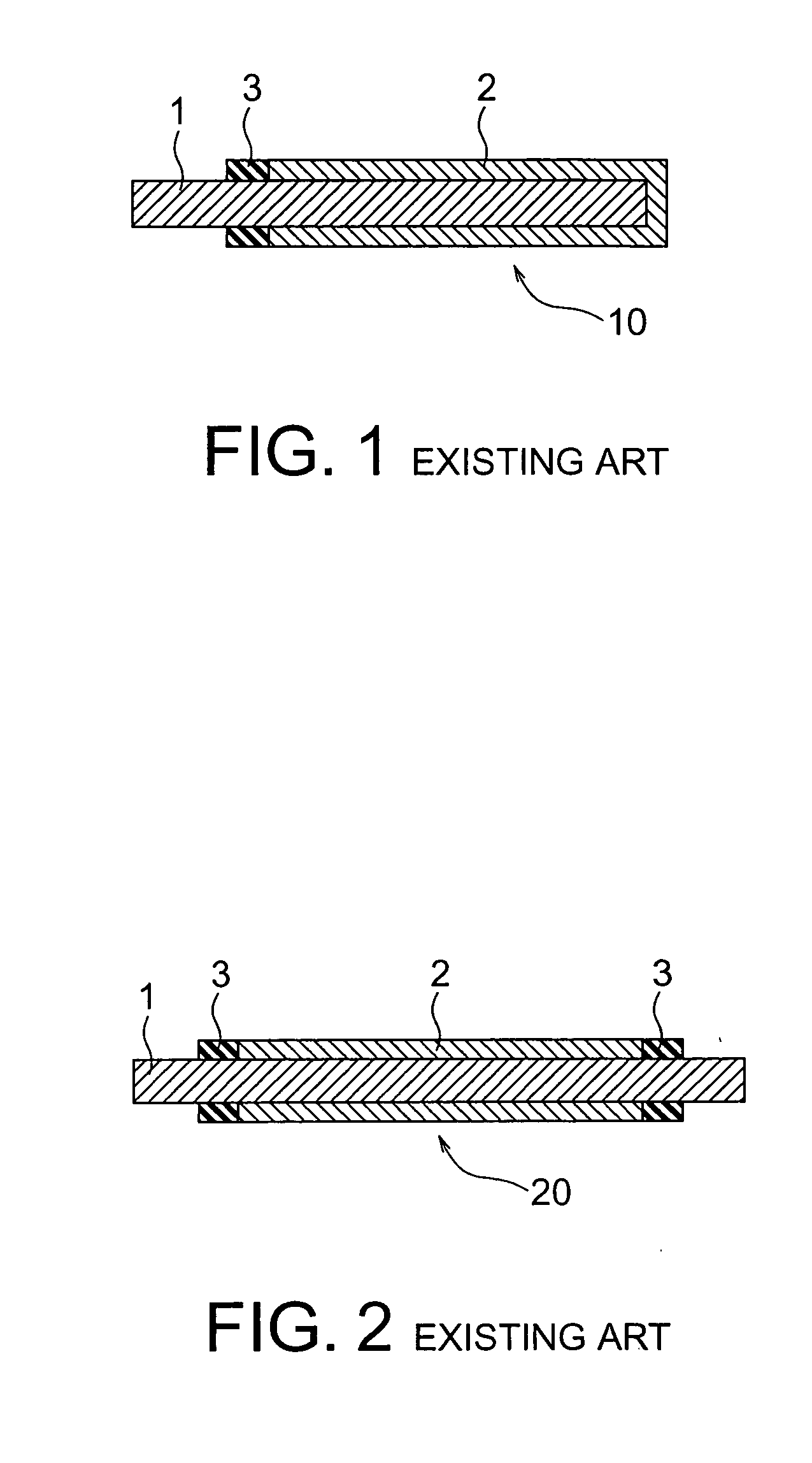
[0059] Each of solid electrolytic capacitor elements 10 is provided with an anode body 1, an oxidized film as a dielectric layer (not shown), a cathode body 2, and an insulation resin member 3, like the solid electrolytic capacitor element 10 shown in FIG. 1. Because the process of manufacturing each of the solid electrolytic capacitor elements 10 is the same as the process described in conjunction with FIG. 1, detailed description thereof will be omitted herein.
[0060] The anode body 1 of each of the solid electrolytic capacitor elements 10 has a substantially plate-shape provided with first and second plate surfaces 1a and 1b as lower and upper surfaces in FIG. 4, two side surfaces 1e and 1f, and first and second end surfaces 1c and 1d as left and right elevational surfaces in FIG. 4. ...
second embodiment
[0069] A second embodiment of this invention is an embodiment that a metal cap is used as the electrically conductive member for electrically connecting between the first end surfaces of the anode bodies. The metal cap has a shape so as to cover a part or the entire of the first end region of the anode body.
[0070]FIG. 5A shows a metal cap 151 used in the second embodiment. FIG. 5B is a sectional view of a laminated solid electrolytic capacitor using therein the metal cap 151.
[0071] Referring to FIG. 5B, the laminated solid electrolytic capacitor comprises four solid electrolytic capacitor elements 10 laminated to one another. Each of solid electrolytic capacitor elements 10 is provided with an anode body 1, an oxidized film as a dielectric layer (not shown), a cathode body 2, and an insulation resin member 3, like the solid electrolytic capacitor element 10 shown in FIG. 1.
[0072] The first end regions of the anode bodies 1 of the solid electrolytic capacitor elements 10 adjacent ...
third embodiment
[0085] In a third embodiment of this invention, a first end region of an anode body of a solid electrolytic capacitor element is previously bent in right angle by the use of a jig before the elements are laminated on one another so that a first or a second plate surface serves as a first end surface extended in area. Consequently, the area of the anode body contacting to an electrically conductive member is increased. When the contacting area is increased, the electrical resistance between the anode body and the electrically conductive member is reduced.
[0086] Referring to FIG. 7, the laminated solid electrolytic capacitor comprises four solid electrolytic capacitor elements 10 laminated to one another. Each of solid electrolytic capacitor elements 10 is provided with an anode body 1, an oxidized film as a dielectric layer (not shown), a cathode body 2, and an insulation resin member 3, like the solid electrolytic capacitor element 10 shown in FIG. 1.
[0087] The first end regions o...
PUM
| Property | Measurement | Unit |
|---|---|---|
| thickness | aaaaa | aaaaa |
| dielectric | aaaaa | aaaaa |
| electrically conductive | aaaaa | aaaaa |
Abstract
Description
Claims
Application Information
 - R&D
- Intellectual Property
- Life Sciences
- Materials
- Tech Scout
- Unparalleled Data Quality
- Higher Quality Content
- 60% Fewer Hallucinations
Browse by: Latest US Patents, China's latest patents, Technical Efficacy Thesaurus, Application Domain, Technology Topic, Popular Technical Reports.
© 2025 PatSnap. All rights reserved.Legal|Privacy policy|Modern Slavery Act Transparency Statement|Sitemap|About US| Contact US: help@patsnap.com