
Method and apparatus for the efficient representation of interpolated video frames for motion-compensated coding

a video frame and motion compensation technology, applied in the field of video compression techniques, can solve the problem of the “wasted” portion of the simd operation, and achieve the effect of increasing the execution speed of the coding process and avoiding wasted portions

Inactive Publication Date: 2005-03-03
LUCENT TECH INC
View PDF8 Cites 17 Cited by
  • Summary
  • Abstract
  • Description
  • Claims
  • Application Information

AI Technical Summary

Benefits of technology

[0009] The present inventor recognized that the use of an alternative organization of the data representation of an interpolated video frame will advantageously result in a significantly more efficient coding process when modern “high-end” processors are used in implementing the codec. In particular, note that many modern processors are specifically optimized for the simultaneous processing of multiple data elements contained in contiguous memory locations. (Such processors are typically referred to as “SIMD” or “Single-Instruction-Multiple-Data” processors.)
[0010] More specifically, the commands of an SIMD processor work by grabbing a relatively large part of memory, such as 64 bits, and operating on 8-bit, 16-bit or 32-bit segments thereof as if they were individual pieces of data. For a non-SIMD instruction, for example, when a register A is added to a register B, the contents of both registers A and B are treated as 64-bit numbers, and a 64-bit result is returned. In an SIMD instruction, on the other hand, register A and B may, for example, be treated as representing 4 separate 16-bit numbers each. Then, each of these 16-bit numbers may be added individually, producing 4 separate 16-bit numbers as a result. Note that in this example, the execution of the SIMD instruction is 4 times faster than executing four instructions with 16-bit data, since 4 commands are executed in parallel, resulting in substantial performance gains. In this way SIMD can increase execution speed by up to 4 times for instructions operating on 16-bit numbers, or 8 times for instructions executing on 8-bit numbers, which is often the case with video and image processing. Other features of these instructions, such as overflow and underflow saturation, further increase the speed of execution significantly, making their use desirable whenever possible.
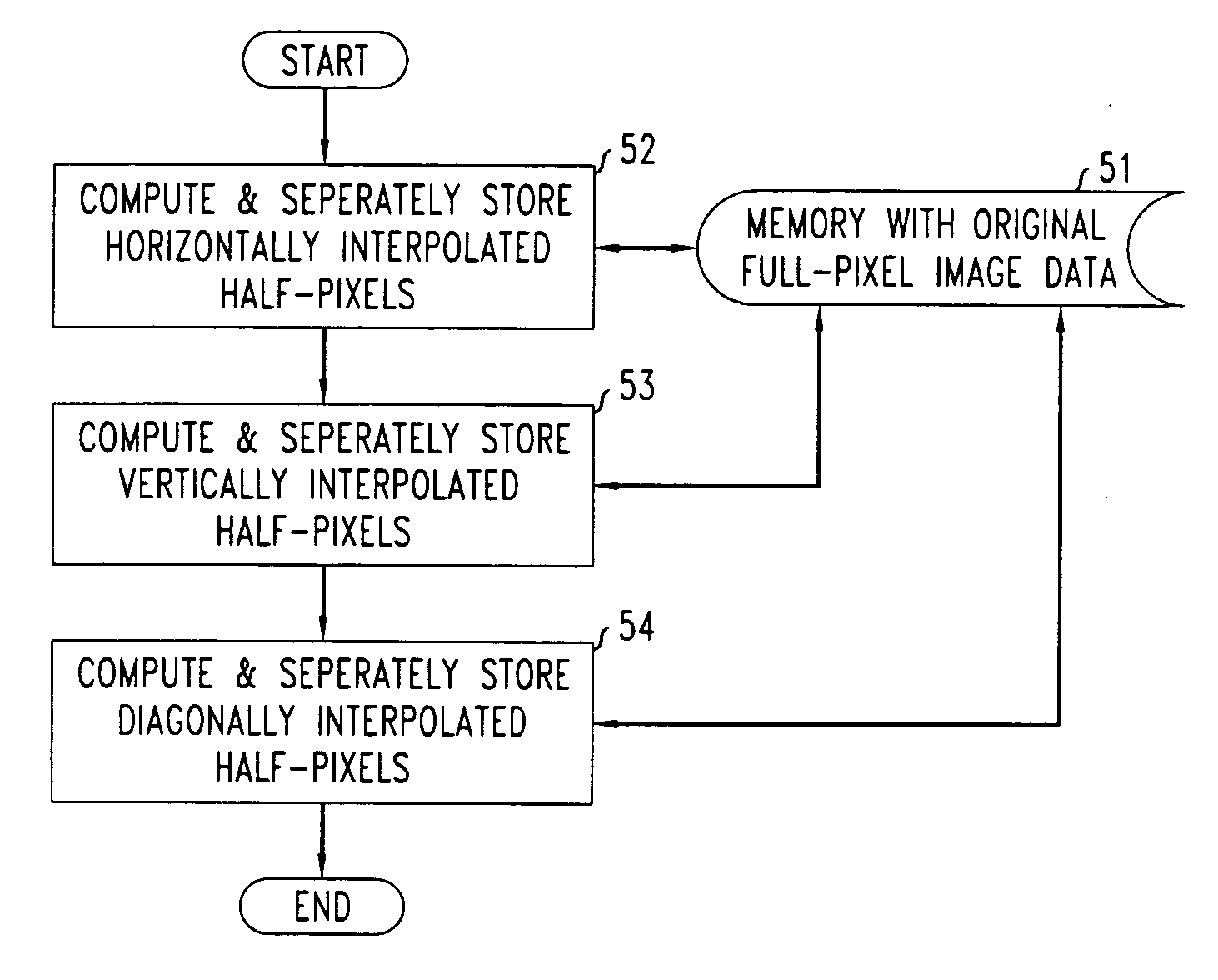
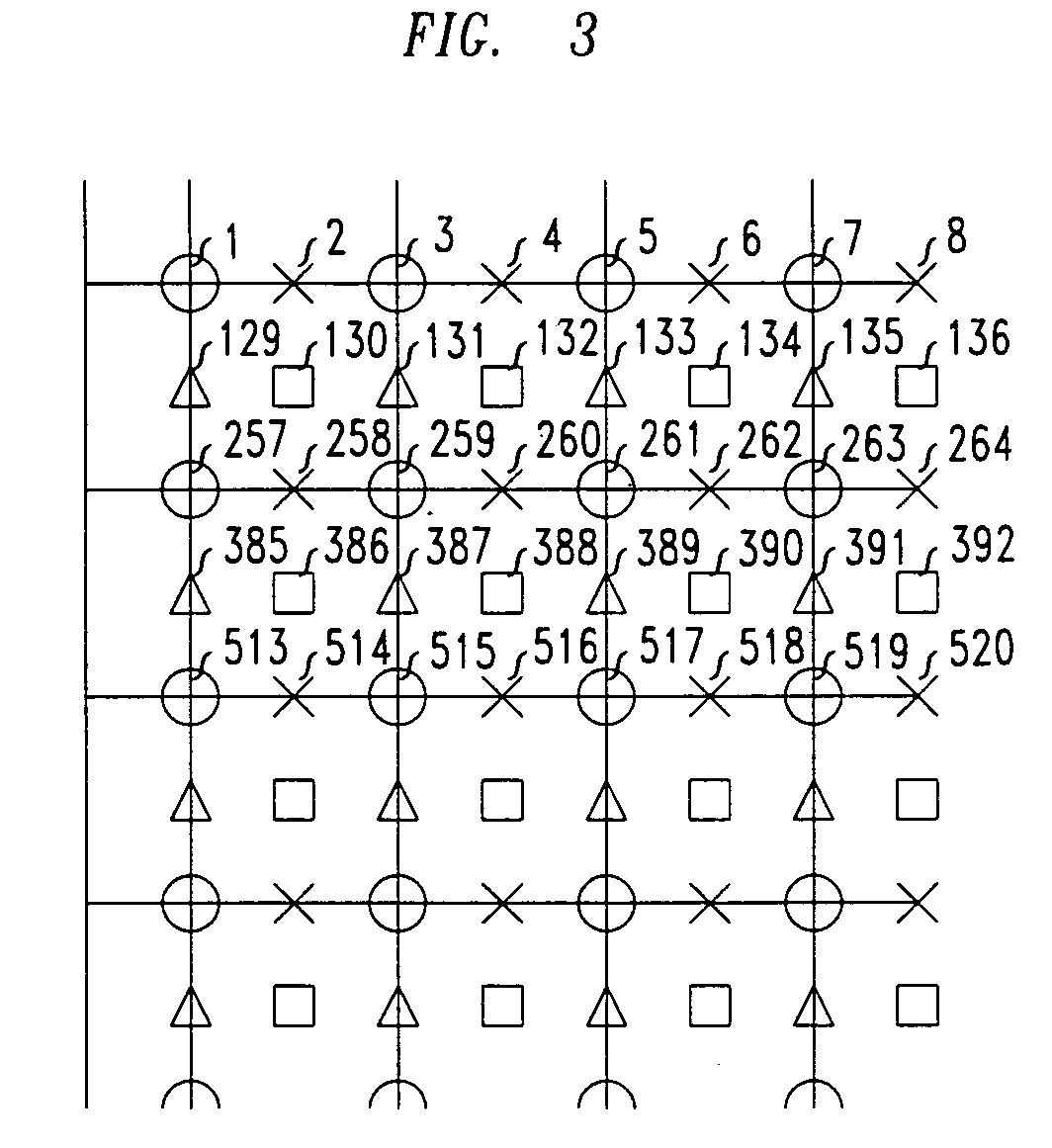
[0012] As such, in accordance with an illustrative embodiment of the present invention, the pixel data of an interpolated video frame is advantageously stored in memory so that full-pixels are located contiguously with other full-pixels, and half-pixels are located contiguously with the appropriate other half-pixels, so that SIMD are advantageously used efficiently, thereby increasing the execution speed of the coding process considerably. More particularly, in accordance with an illustrative embodiment of the present invention in which half-pixel interpolations are employed, the full-pixels of the original image or portion (e.g., block) thereof are stored in a first set of contiguous memory locations; the half-pixels corresponding to data interpolated between horizontally adjacent full-pixels of the original image or portion (e.g., block) thereof are stored in a second set of contiguous memory locations; the half-pixels corresponding to data interpolated between vertically adjacent full-pixels of the original image or portion (e.g., block) thereof are stored in a third set of contiguous memory locations; and the half-pixels corresponding to data interpolated between diagonally adjacent full-pixels of the original image or portion (e.g., block) thereof are stored in a fourth set of contiguous memory locations.

Problems solved by technology

Otherwise, every other pixel (in the case of half-pixel interpolation) or more (in the case of quarter-pixel or eighth-pixel interpolation) will result in a “wasted” portion of the SIMD operation.

Method used


Image

  • Method and apparatus for the efficient representation of interpolated video frames for motion-compensated coding
  • Method and apparatus for the efficient representation of interpolated video frames for motion-compensated coding
  • Method and apparatus for the efficient representation of interpolated video frames for motion-compensated coding

Examples


Embodiment Construction

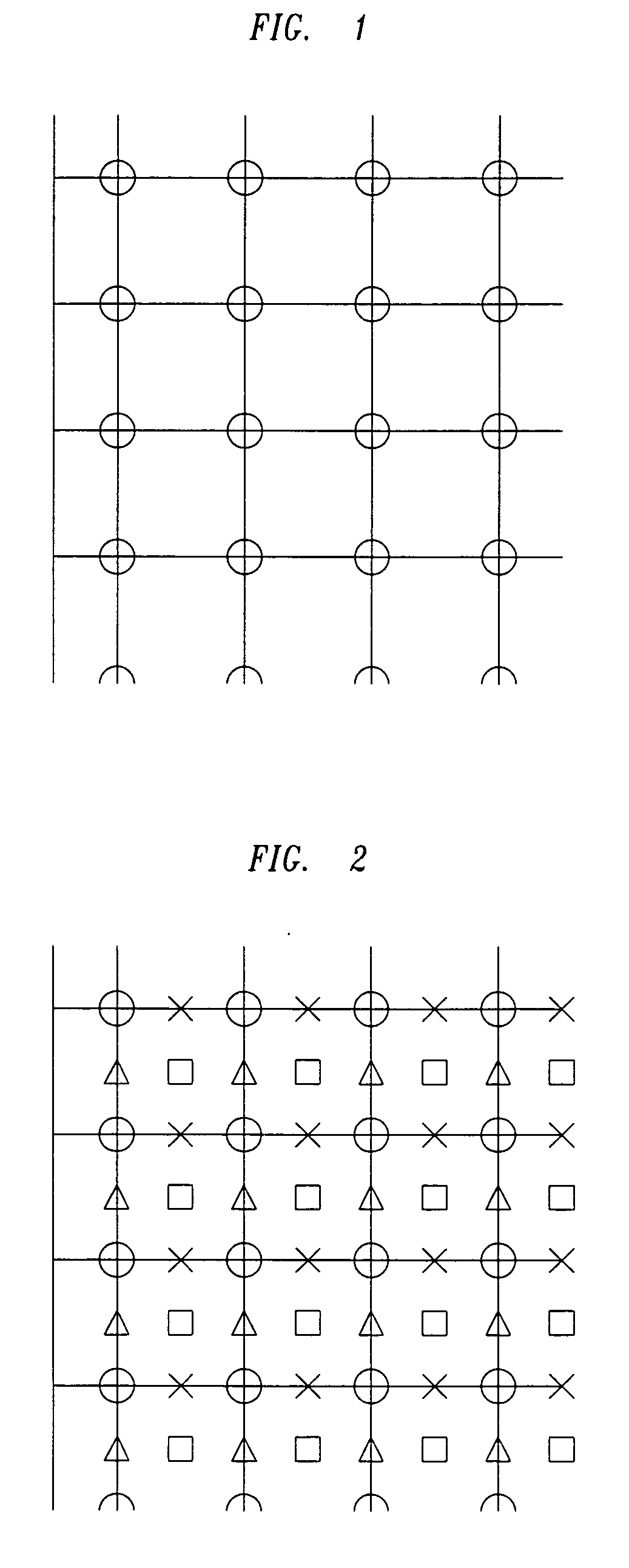
[0018]FIG. 1 shows a portion of an illustrative image of a video frame. Each dot in the figure (located at the intersection of a pair of perpendicular lines) represents the location of a pixel in the original image. Note that an image is typically represented as a 2-dimensional collection of pixels with particular “values” for the brightness and / or color of each pixel.

[0019]FIG. 2 shows a portion of an illustrative image of a video frame which has been interpolated to a half-pixel representation. In particular, the figure shows both the original full-pixels and all of the half-pixels that would be calculated for such a (half-pixel) interpolated image. Generating half-pixel representations may be computationally intensive, although mathematically the values of these half-pixels are usually just the average of the surrounding pixel values.

[0020] Specifically, in FIG. 2 the original full-pixels are represented as dots. Half-pixels created by averaging horizontally adjacent dots are m...


PUM


Abstract

An efficient representation of an interpolated video frame when used with Single-Instruction-Multiple-Data processors implementing motion-compensated coding. The pixel data of a half-pixel interpolated video frame is stored in memory so that the full-pixels of the original image are stored in a first set of contiguous memory locations; the half-pixels interpolated between horizontally adjacent full-pixels are stored in a second set of contiguous memory locations; the half-pixels interpolated between vertically adjacent full-pixels are stored in a third set of contiguous memory locations; and the half-pixels interpolated between diagonally adjacent full-pixels are stored in a fourth set of contiguous memory locations.

Description

FIELD OF THE INVENTION [0001] The present invention relates generally to the field of video compression techniques, and in particular to a method and apparatus for the efficient representation of interpolated video frames particularly for use in motion-compensated coding. BACKGROUND OF THE INVENTION [0002] In video compression, video encoding is a major computational bottleneck. The demands of video processing have been a significant driver in the design of processors, computer systems, and communication networks, and will continue to be an increasingly important design specification as video applications, such as real-time video delivered over the Internet, become more common. Some of these applications are particularly demanding of computational resources, and so, to make these applications available to more consumers, very efficient implementations of the encoding algorithms are required. [0003] In fact, compression and decompression of sequences of video images, either for trans...

Claims


Application Information

Patent Timeline
Patent Type & Authority Applications(United States)
IPC IPC(8): H04N5/85H04N7/12H04N7/26H04N7/36H04N7/50H04N9/804
CPCH04N5/85H04N9/8042H04N19/523H04N19/433H04N19/61
Inventor MCGOWAN, JAMES WILLIAM
Owner LUCENT TECH INC
Learn More