Dispersion compensation control method and apparatus thereof and optical transmission method and system thereof

a technology of dispersion compensation and control method, applied in electromagnetic transmission, transmission, time-division optical multiplex system, etc., can solve the problems of inability to accurately monitor waveform distortion, inability to extract clocks to establish synchronization, and deterioration of optical pulse quality, so as to achieve precise chromatic dispersion control and control dispersion compensation

Inactive Publication Date: 2005-03-03
NAT INST OF INFORMATION & COMM TECH
View PDF1 Cites 24 Cited by
  • Summary
  • Abstract
  • Description
  • Claims
  • Application Information

AI Technical Summary

Benefits of technology

[0022] Preferably, the controller controls first an amount of dispersion compensation of the dispersion compensator so that the power of the predetermined frequency component measured by the power monitor becomes lower and thereafter dispersion slope of the dispersion compensator so that the power of the predetermined frequency component measured by the power monitor becomes lower. This operation makes it possible to realize precise chromatic dispersion control suitable for signal reception.
[0023] Preferably, the optical transmitter comprises a pulse light source to pulse-oscillate at a frequency of the base rate, an optical divider to divide an output pulse light from the pulse light source into a plurality of channels, a plurality of data modulators to modulate each pulse light divided by the optical divider with respective transmission data, an optical adjuster to adjust so that an amplitude or optical phase of at least one pulse signal light of a predetermined channel within the pulse signal lights of the respective channels generated by the plurality of data modulators is different from amplitudes or optical phases of the pulse signal lights of the rest of the channels, and an optical multiplexer to time-division-multiplex the pulse signal lights of the respective channels. Accordingly, a spectrum component having a predetermined frequency is easily superimposed on an OTDM signal light in a simple configuration.
[0024] According to the invention, it is possible to adequately control dispersion compensation of an ultra high-speed optical pulse signal that is too fast to be directly converted into an electrical signal. In addition, the invention realizes transmission of an ultra high-speed optical signal as fast as 160 Gbps.

Problems solved by technology

However, since response speed of an electric receiver is at most 50 to 60 GHz, it is impossible to extract clocks to establish synchronization even if optical pulse signals of 160 Gbps or more are directly received.
Generally speaking, the quality of an optical pulse deteriorates when an ultra high-speed optical pulse is demultiplexed into low-speed optical pulses.
Accordingly, in a conventional configuration, it was impossible to accurately monitor waveform distortion due to chromatic dispersion in an optical fiber transmission line.
As a result, control of dispersion compensation was sometimes performed inaccurately.

Method used


Image

  • Dispersion compensation control method and apparatus thereof and optical transmission method and system thereof
  • Dispersion compensation control method and apparatus thereof and optical transmission method and system thereof
  • Dispersion compensation control method and apparatus thereof and optical transmission method and system thereof

Examples


Embodiment Construction

[0032] Explanatory embodiments of the invention are explained below in detail with reference to the drawings.

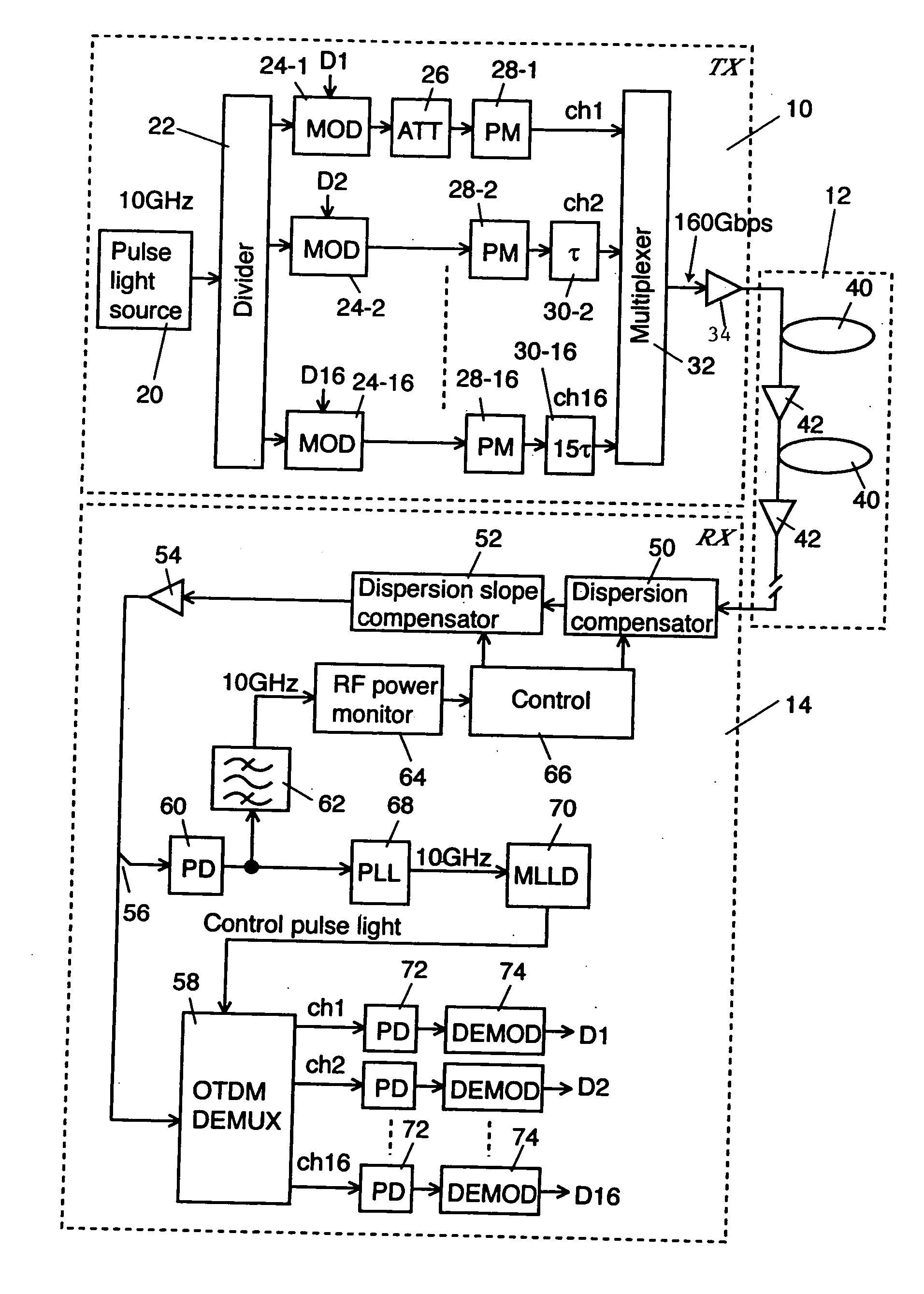
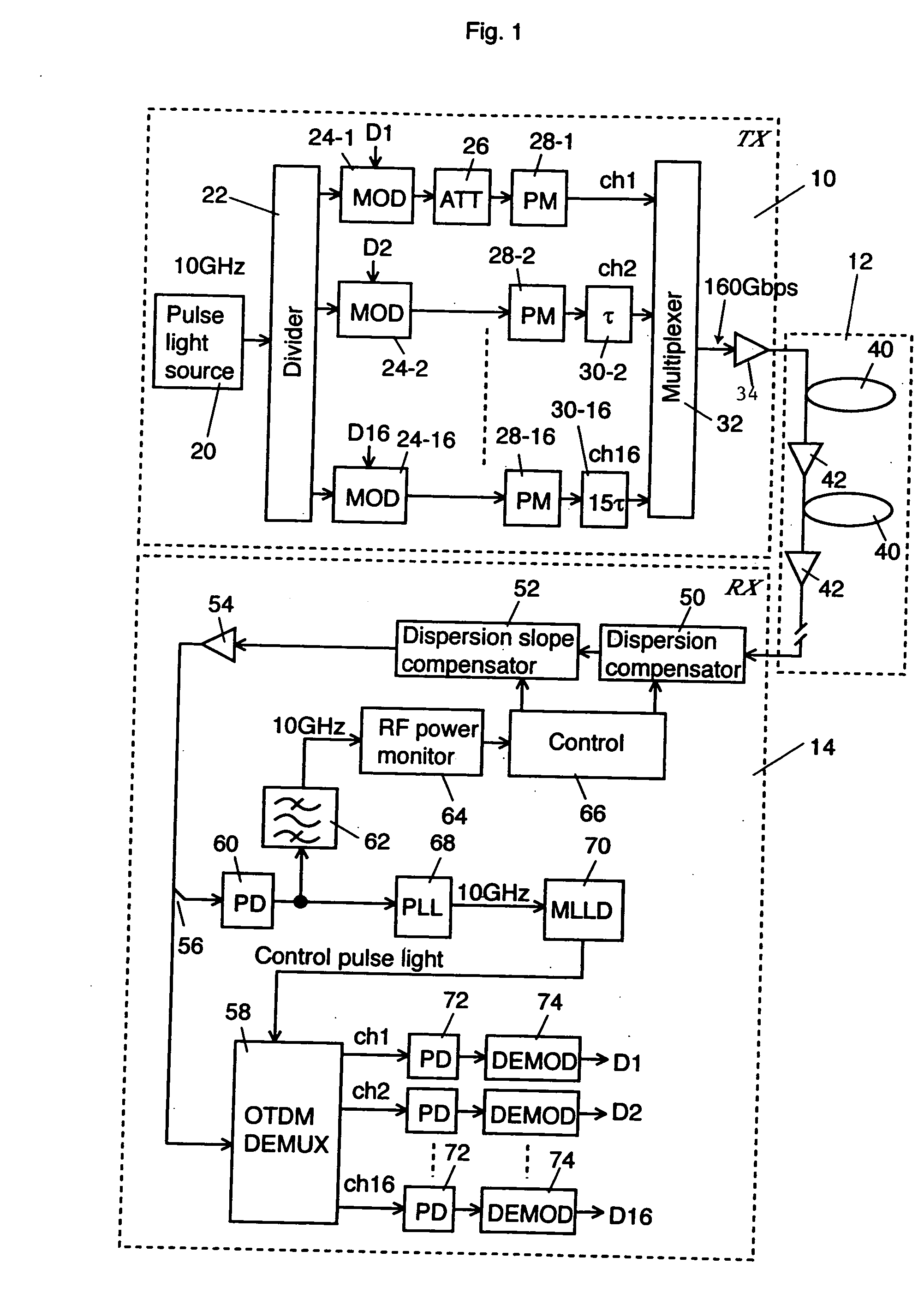
[0033]FIG. 1 shows a schematic block diagram of an optical transmission system in which an explanatory embodiment according to one embodiment of the invention is applied.

[0034] The optical transmission system according to the explanatory embodiment comprises an optical transmitter 10, an optical transmission line 12, and an optical receiver 14. In this explanatory embodiment, the optical transmitter 10 time-division-multiplexes 16 channels of 10 Gbps optical signals and outputs the multiplexed signals into the optical transmission line 12. Accordingly, an optical signal of 160 Gbps propagates in the optical transmission line 12.

[0035] The configuration and operation of the optical transmitter 10 is explained. A pulse light source 20 outputs an optical pulse having a single wavelength λs and a basic repetition frequency (a base rate) of 10 GHz. An optical divider 22 divides...


PUM


Abstract

An optical transmitter transmits an OTDM signal light on which a spectrum component of a predetermined frequency is superimposed into an optical transmission line. A photodetector in an optical receiver converts the OTDM signal light output from the optical transmission line into an electrical signal. An electric bandpass filter extracts a component having the predetermined frequency out of the output from the photodetector. An RF power monitor measures power of the predetermined frequency component out of the output from the filter. A controller controls first an amount of dispersion compensation of a chromatic dispersion compensator so that the power of the predetermined frequency component becomes lower, and thereafter a dispersion slope of the chromatic dispersion compensator so that the power of the predetermined frequency component becomes lower.

Description

CROSS REFERENCE TO RELATED APPLICATIONS [0001] This application claims priority to Japanese Patent Application No. 2003-307030, filed Aug. 29, 2003, the entire contents of which are incorporated herein by reference. FIELD OF THE INVENTION [0002] This invention relates to a method and apparatus to control dispersion compensation, and an optical transmission method and system thereof. BACKGROUND OF THE INVENTION [0003] In optical fiber transmission systems, a bit rate as fast as 160 Gbps or more per wavelength is about to be realized. However, since response speed of an electric receiver is at most 50 to 60 GHz, it is impossible to extract clocks to establish synchronization even if optical pulse signals of 160 Gbps or more are directly received. [0004] In an optical fiber transmission system using an ultra high-speed optical pulse signal, for example an optical pulse signal of 160 Gbps, in which photoelectric conversion is difficult, it is necessary to precisely control chromatic dis...

Claims


Application Information

Patent Timeline
Patent Type & Authority Applications(United States)
IPC IPC(8): H04B10/2507H04B10/07H04B10/2513H04B10/508H04B10/54H04B10/548H04B10/564H04J14/08
CPCH04B10/504H04B10/25137
Inventor MIYAZAKI, TETSUYA
Owner NAT INST OF INFORMATION & COMM TECH
Why Eureka
Try Eureka