Charging device and image forming apparatus

Inactive Publication Date: 2005-03-03
KONICA MINOLTA BUSINESS TECH INC
View PDF9 Cites 7 Cited by
  • Summary
  • Abstract
  • Description
  • Claims
  • Application Information

AI Technical Summary

Benefits of technology

[0017] Accordingly, an object of the invention is to provide a charging device for use in an image forming apparatus, including a discharging electrode supplied with a high voltage, a stabilizer plate having an opening on a side opposed to a charge target member, and a grid arranged in the opening of the stabilizer plate and supplied with a grid voltage, and particularly to provide the charging device, which can exhi

Problems solved by technology

However, components of a charging device in an image forming apparatus are oxidized after it is used many times even if the components are made of stainless steel.
When at least one of the discharging electrode, stabilizer plate and grid is oxidized to a certain extent, the discharging device, which is configured, e.g., to charge uniformly a surface of an image carrying member, cannot charge various portions of the surface of the image carrying member to

Method used


Image

  • Charging device and image forming apparatus
  • Charging device and image forming apparatus
  • Charging device and image forming apparatus

Examples


Example

[0037] A charging device of a first embodiment of the invention basically has the following structure.

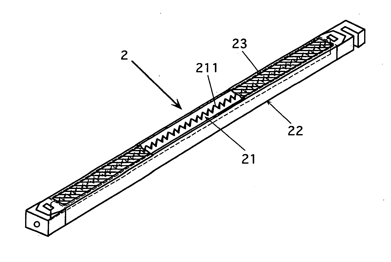
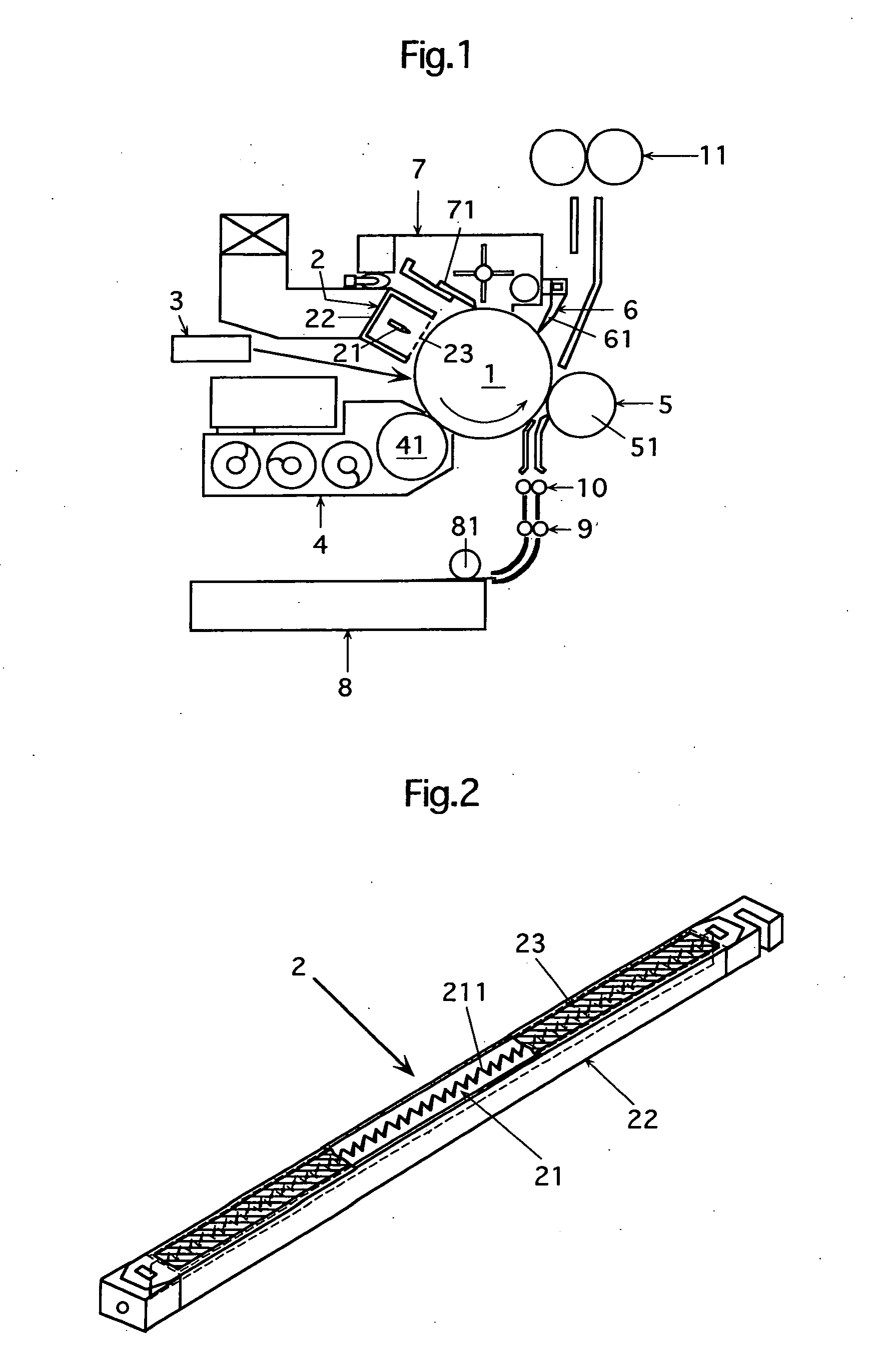
[0038] The charging device includes a discharging electrode to be supplied with a high voltage, a stabilizer plate (shield casing) having an opening on a side to be opposed to a charge target member (a member to be charged) and accommodating the discharging electrode, and a grid arranged in the opening of the stabilizer plate and to be supplied with a grid voltage.

[0039] At least one of the discharging electrode, the stabilizer plate and the grid is made of an electrically conductive material containing 30% or more of nickel by weight.

[0040] The conductive material containing 30% or more of nickel (Ni) by weight may be a Ni—Fe alloy or a Ni—Cr—Fe alloy having a nickel content of 30 wt % (30% by weight) or more. In any case, it is preferable that the conductive material has a nickel content of 40 wt % (40% by weight) or more. The nickel content of the conductive material may be 10...

Example

[0057] According to the charging device of the second embodiment, at least one of three members, i.e., the discharging electrode, stabilizer plate and grid is plated with the nickel or platinum, which is a material having a high resistance to oxidation, and the plating is effected at a high rate from 30% to 80% by weight with respect to whole weight of the plated member. Even after long-term use, therefore, oxidation of the plated member(s) can be suppressed, and thus the whole charging device can exhibit an intended charging performance for a long term.

[0058] The image forming apparatus provided with the charging device of the second embodiment can form good images with less image noises for a long term.

[0059] Both the charging devices of the foregoing embodiments can exhibit an intended charging performance for long-term use, as compared with conventional structures, in which all components are made of stainless steel, or a discharging electrode is made of a conductive material ...

Example

[0103] The charging device of the comparative experiment 2 suppressed the rising of the surface potential of the photosensitive member further significantly, as compared with the charging device of the foregoing comparative experiment 1 employing the grid of SUS304 having the Ni-content of 10 wt %, and thus represented the effect of the nickel plating. It is apparent that the nickel plating at a rate of 30 wt % or more with respect to the whole weight of the grid can sufficiently achieve the effect of the nickel plating.

[0104] In the charging device of the experiment 1, the Ni-content of the grid material was changed to various values. Also, in the charging device of the experiment 2, the weight rate of the nickel plating with respect to the grid body was changed to various values. Under these conditions, image formation was performed with a chart of B / W rate of 5% for 90 hours, and thereafter the surface potential of the photosensitive drum rose as illustrated in FIG. 13. The foll...


PUM


Abstract

A charging device has a discharging electrode, a stabilizer plate having a rectangular section and accommodating the discharging electrode, and a grid arranged in a opening of the stabilizer plate, and at least one member of the discharging electrode, the stabilizer plate and the grid is made of an electrically conductive material containing 30% or more of nickel by weight or is plated with nickel or platinum at a rate from 30% to 80% by weight with respect to whole weight of the plated member. An image forming apparatus employs the charging device.

Description

CROSS-REFERENCE TO RELATED APPLICATION [0001] This application is based on Japanese patent application No.2003-305757 filed in Japan on Aug. 29, 2003, and Japanese patent application No.2004-40890 filed in Japan on Feb. 18, 2004, the entire contents of which are hereby incorporated by reference. BACKGROUND OF THE INVENTION [0002] 1. Field of the Invention [0003] The invention relates to a charging device for use in an image forming apparatus as well as the image forming apparatus. [0004] 2. Description of Related Art [0005] Charging devices are employed, e.g., in electrophotographic image forming apparatuses and particularly in various kinds of recording devices such as electrophotographic copying machines, facsimile machines and printers, and electrophotographic display devices. [0006] For example, in an electrophotographic recording device, a charging device charges a surface of an image carrying member to bear a uniform potential, and image exposure corresponding to an image to b...

Claims


Application Information

Patent Timeline
IPC IPC(8): G03G15/02H01T19/04
CPCG03G2215/028G03G15/0266
Inventor NAKANE, YOSHIKIOKAZAKI, FUTOSHIKAWASAKI, TOMOHIROOGAWA, SHINJI
Owner KONICA MINOLTA BUSINESS TECH INC
Why Eureka
Try Eureka