Deepwell reel

a reel and deepwell technology, applied in special-purpose vessels, machines/engines, liquid fuel engines, etc., can solve the problems of putting feet into the mud, fire safety systems need a large supply of seawater, and provide plumbing problems with the unpredictability of leg position, etc., to achieve the effect of flow, power and strength

Inactive Publication Date: 2005-03-03
BAUGH BENTON F
View PDF3 Cites 29 Cited by
  • Summary
  • Abstract
  • Description
  • Claims
  • Application Information

AI Technical Summary

Benefits of technology

[0013] The object of this invention is to provide a reel and hose assembly which will allow flow, power, and strength to be handled in a single member.
[0016] Another object of the present invention is to provide for the automatic stopping of the reel when the hose if fully deployed.

Problems solved by technology

First, when the jackup rig jacks itself out of the water, it pushes feet down into the mud.
Thirdly, fire safety systems need a large supply of seawater for fire safety.
This is workable but provides plumbing problems with the unpredictability of the leg position. custom pumping or large flexible hoses are required to compensate for this unpredictability.
Additionally, the pump is difficult to retrieve in case of need for servicing.
A deepwell tower is an expensive construction and provides the disadvantage of providing a large surface area in the wave zone.
They are typically short lived and expensive to repair.
This makes for a complicated system with the reels being of different diameters and therefore different operating speeds.

Method used


Image

  • Deepwell reel
  • Deepwell reel
  • Deepwell reel

Examples


Embodiment Construction

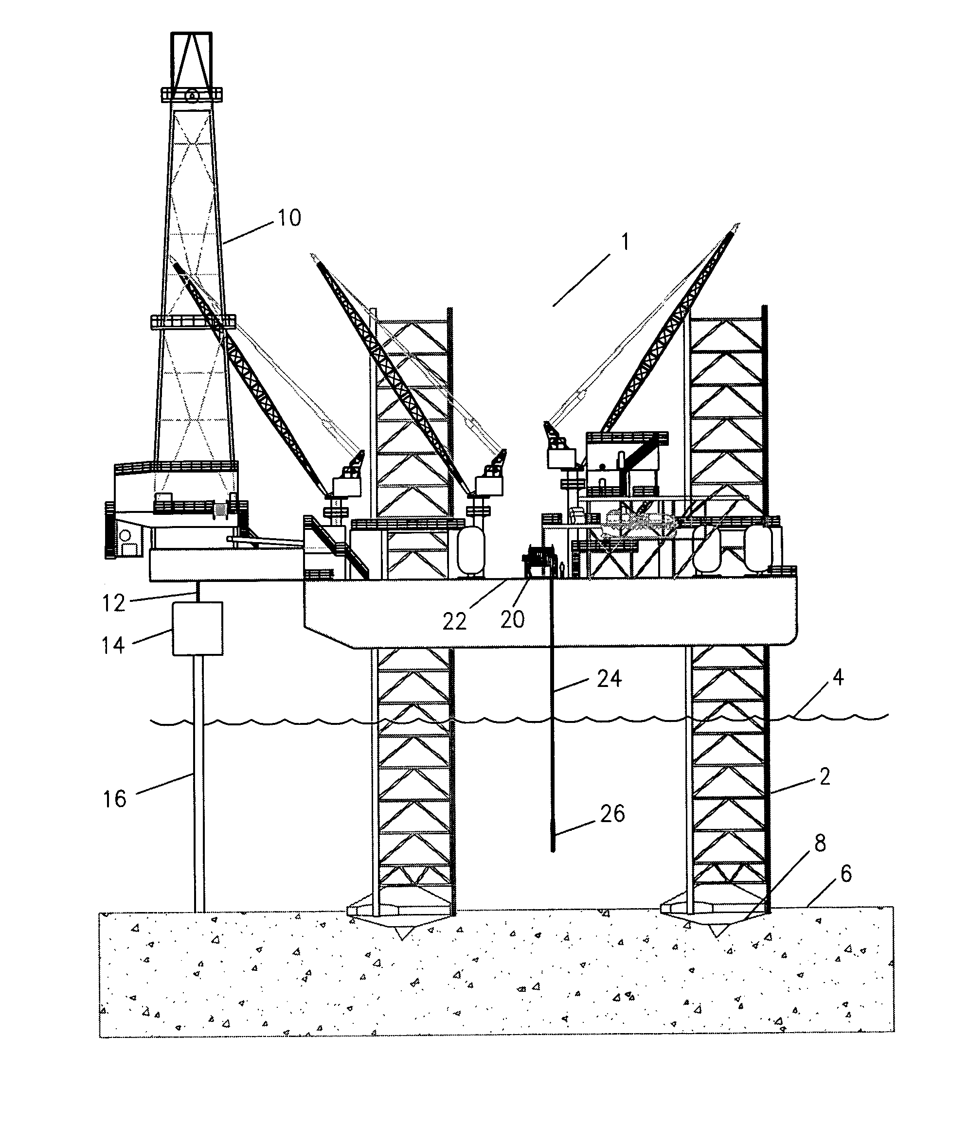
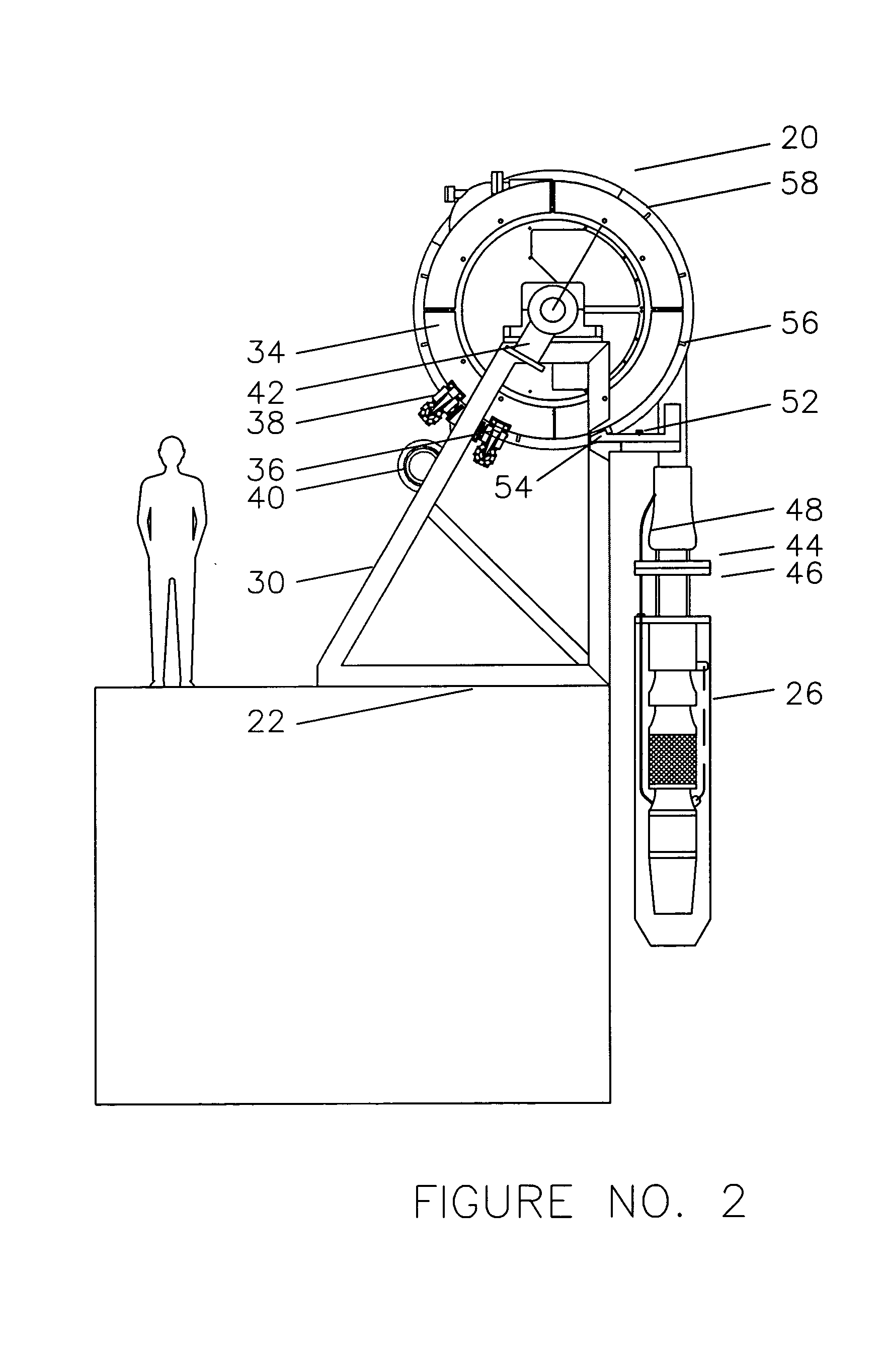
[0022]FIG. 1 shows a jackup rig 1 as would be landed on the ocean floor for the drilling of an oil or gas well. Legs 2 are shown going thru the ocean surface 4 and penetrating the seafloor 6 at 8.

[0023] Drilling rig 10 is shown supported on the jackup rig 1 with drill pipe 12 extending downwardly thru the blowout prevention equipment 14 and casing pipes 16.

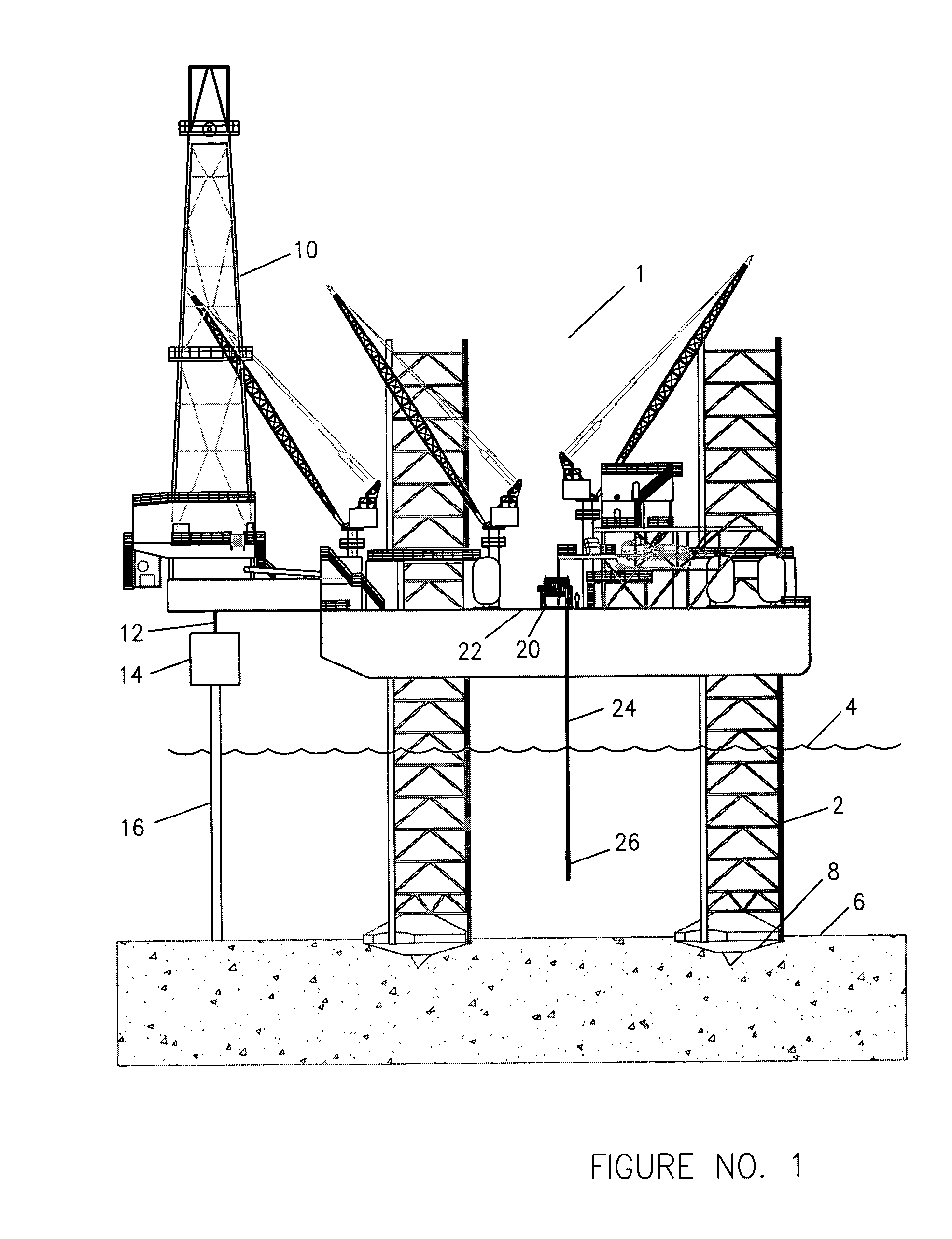
[0024] Reel 20 is shown setting on the deck 22 of jackup rig 1 with hose 24 extending downwardly to the supported pump 26.

[0025] Referring now to FIG. 2, reel 20 is supported on deck 22 by frame 30 and provides brake drum 34, brake assemblies 36 and 38, drive motor 40, and swivel 42.

[0026] Hose 24 has a lower end 44 which connects directly to the upper end 46 of the pump 26. Wires 48 exit from the hose 24 to power the pump 26.

[0027] When arm 50 is moved out of the page the arm 50 pivots about axle 52 and causes the end 54 to move into the page and engage one of the ribs 56 on the side of the spool 58.

[0028] Referring now to ...


PUM


Abstract

A method of providing for seawater supply to an offshore jackup rig comprising suspending a pump from a hose which is unreeled from a reel on the jackup rig, the hose comprising fluid flow capacity for allowing seawater to be pumped from ocean depths up to the jackup rig, axial tensile capacity members within the wall of the hose to support the pump and the column of pumped water, and electricity carrying members within the wall of the hose to power the pump, a gland for the insertion of an electrical umbilical within the internal bore of the hose, and laying the hose horizontally on the deck of the jackup to insert the electrical umbilical within the hose.

Description

CROSS-REFERENCE TO RELATED APPLICATIONS [0001] N / A STATEMENT REGARDING FEDERALLY SPONSORED RESEARCH OR DEVELOPMENT [0002] N / A INCORPORATION-BY-REFERENCE OF MATERIAL SUBMITTED ON A COMPACT DISK [0003] N / A BACKGROUND OF THE INVENTION [0004] The field of this invention of that of special hose and reel assemblies for the support of jack-up rigs in the offshore oil and gas drilling industry. On land, drilling rigs simply sit on the ground. In very deep water, the rigs must float and are held in position by anchor lines or by dynamic position, which means running the propellers at all times. [0005] Between dry land and deep offshore there is a shallow water situation in which a jackup rig can move to a location, put down legs, and literally jack itself out of the water. It will typically have an air gap of 20 to 50 feet between the bottom of the rig and the mean height of the ocean waves. In order to maintain this gap at different depths, the legs must have the ability to extend down diff...

Claims


Application Information

Patent Timeline
Patent Type & Authority Applications(United States)
IPC IPC(8): E02B17/00E21B17/20F04D13/08F04D29/60
CPCE02B17/021E02B2017/006F04D13/086E21B17/206F04D29/605E02B2017/0082
Inventor BAUGH, BENTON F.
Owner BAUGH BENTON F
Why Eureka
Try Eureka