Method of manufacturing disc-shaped recording medium

a technology of disc-shaped recording media and manufacturing method, which is applied in the field of manufacturing method of disc-shaped recording medium, can solve the problems of fixed cutter knife, inability to follow, and increase manufacturing cost, so as to reduce the swelling of resin, improve the manufacturing yield, and reduce the effect of cutting wastag

a technology of disc-shaped recording media and manufacturing method, which is applied in the field of manufacturing method of disc-shaped recording medium, can solve the problems of fixed cutter knife, inability to follow, and increase manufacturing cost, so as to reduce the swelling of resin, improve the manufacturing yield, and reduce the effect of cutting wastag

US20050048202A1Inactive Publication Date: 2005-03-03TDK CORPARATION

Image

  • Method of manufacturing disc-shaped recording medium
  • Method of manufacturing disc-shaped recording medium
  • Method of manufacturing disc-shaped recording medium

Examples


Embodiment Construction

[0026]

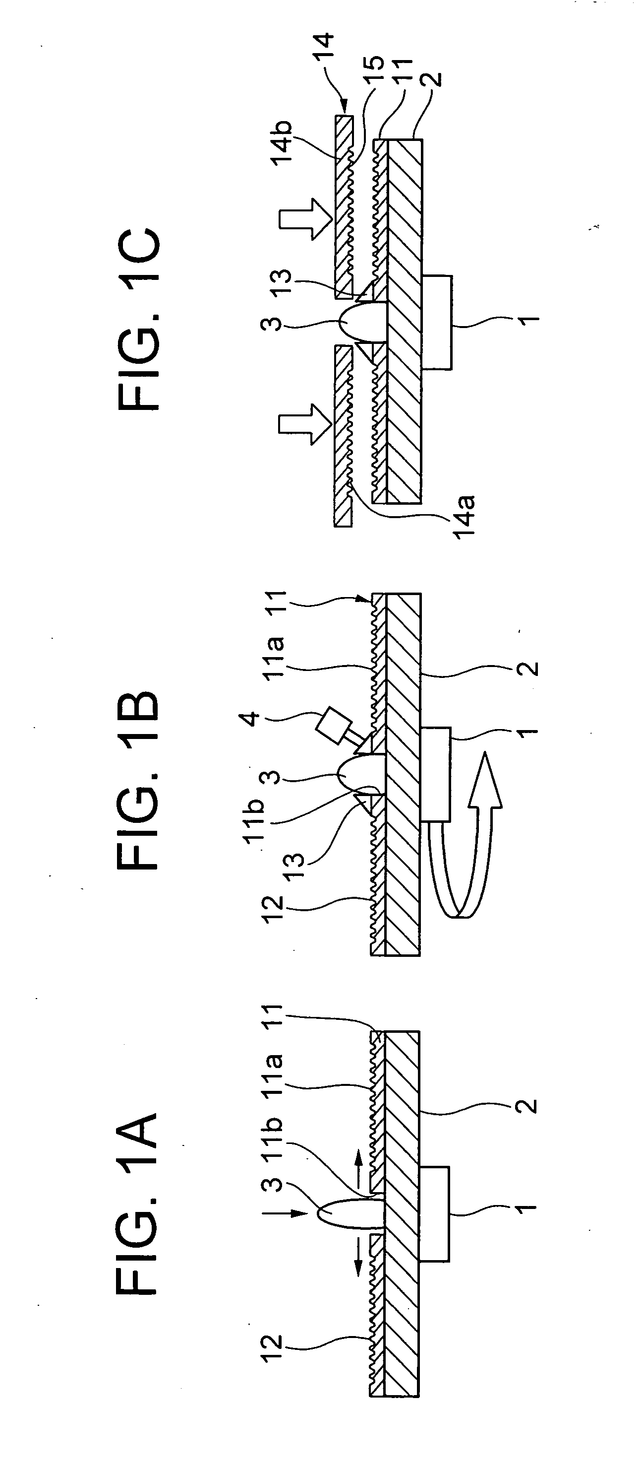
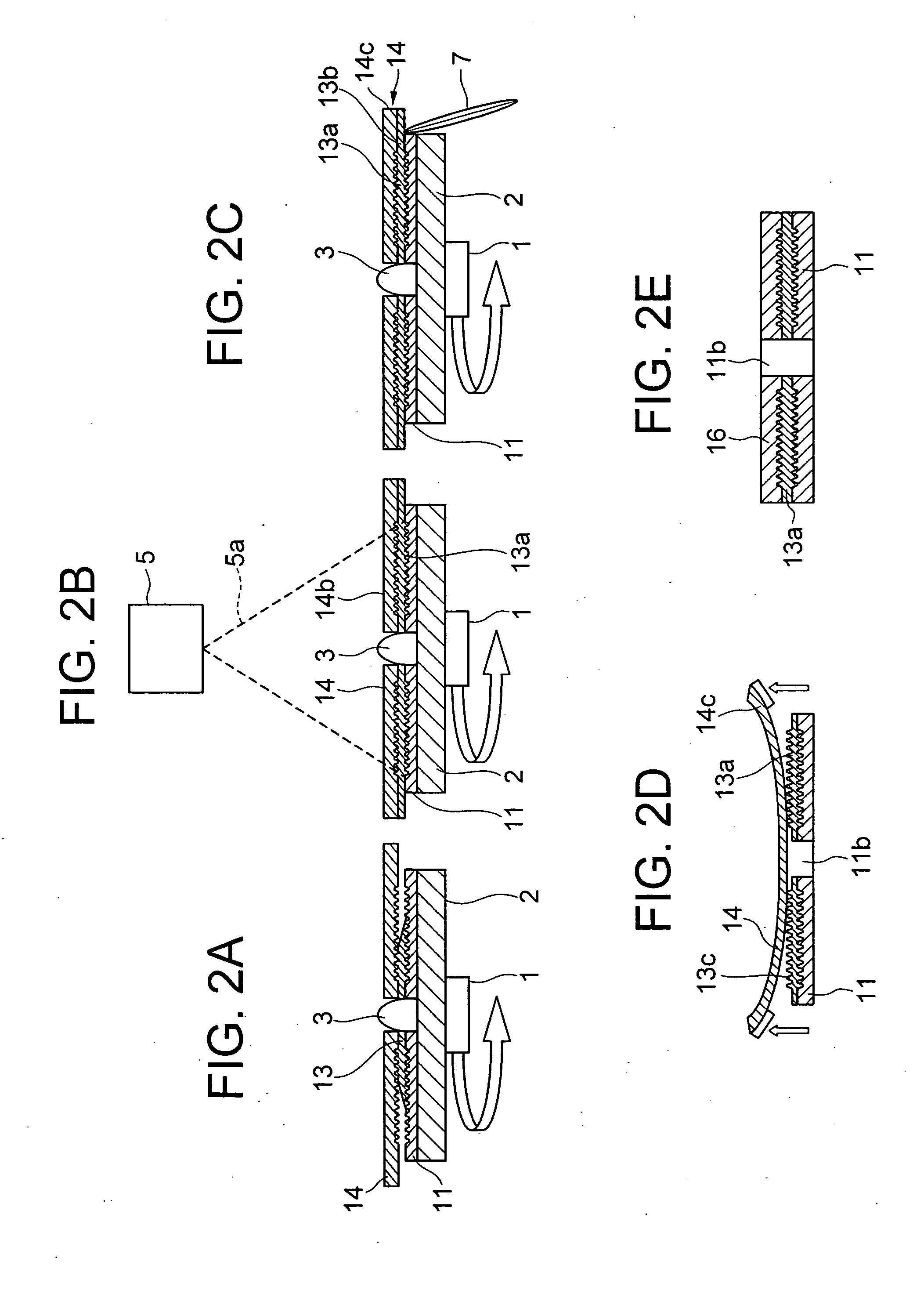
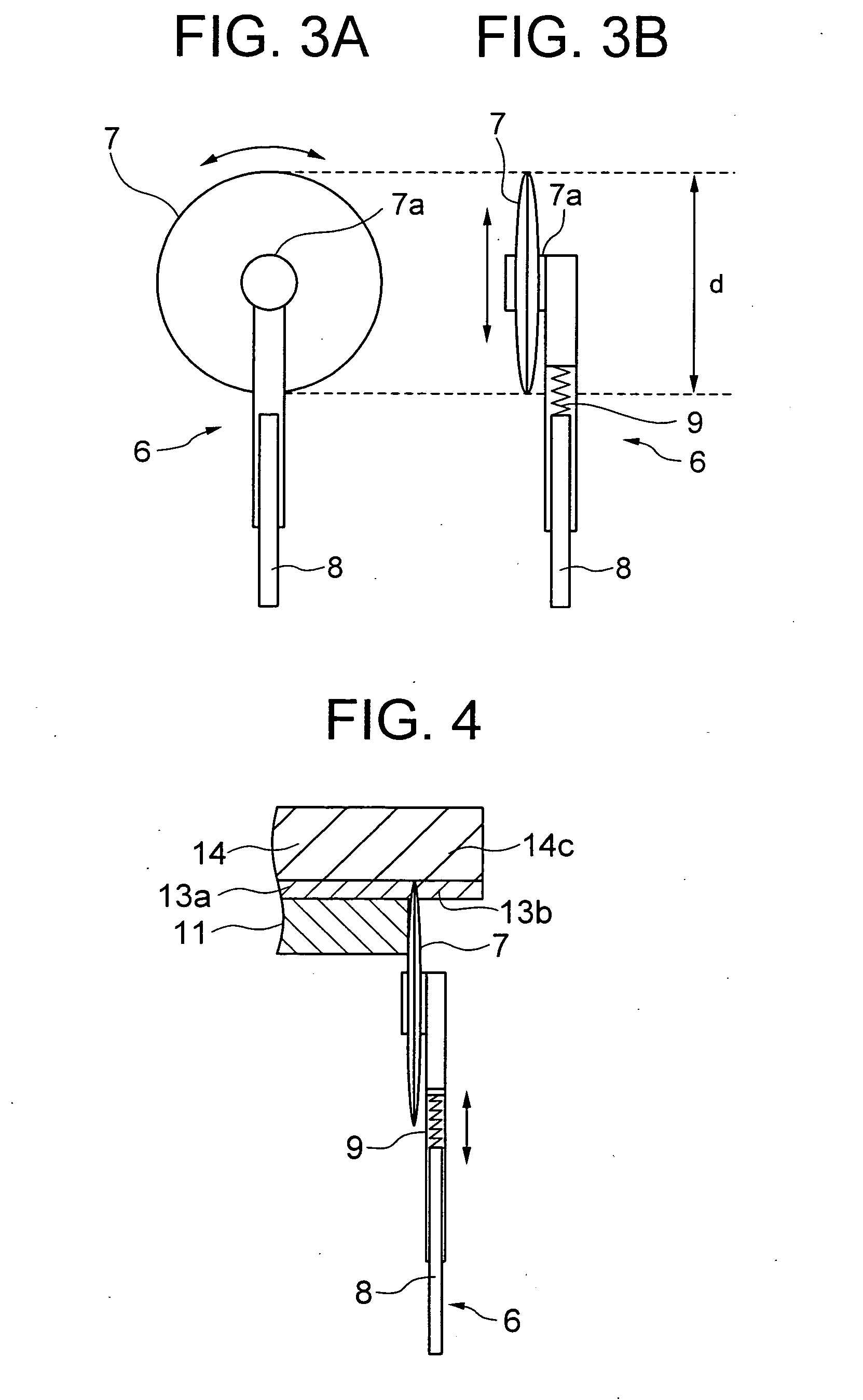
[0027]FIGS. 1A to 1C are side sectional views each showing a process of manufacturing a 2-layered optical disc in a first embodiment. FIGS. 2A to 2E are side sectional views showing processes of manufacturing the 2-layered optical disc, which are executed subsequently to the process in FIG. 1C. FIG. 3A is a front view of a circle cutter capable of executing a notch forming process in FIG. 2C. FIG. 3B is a side view thereof. FIG. 4 is an enlarged principal side sectional view showing how the notch forming process in FIG. 2C is executed by the circle cutter in FIG. 3A. FIG. 5 is an enlarged principal side sectional view showing how the notch forming process in FIG. 2C is obliquely executed by the circle cutter in FIG. 3A.

[0028] The first embodiment exemplifies a method of manufacturing a single-sided 2-layered type optical disc. To be specific, as shown in FIG. 1A, a stage 2 for spin coating is so constructed as to be rotated by a motor (unillustrated) through a rotary shaft 1....


PUM

PropertyMeasurementUnit
diameteraaaaaaaaaa
diameteraaaaaaaaaa
densityaaaaaaaaaa

Abstract

Disclosed is a disc-shaped recording medium manufacturing method capable of making it difficult to leave the cutting wastage produced upon forming a notch for exfoliating a stamper on a disc-shaped substrate in the case of adopting a stamper-based transfer method, and surely forming the notch to improve a manufacturing yield. This disc-shaped recording medium manufacturing method is that a spacer layer having recording faces on both surfaces thereof is formed between the disc-shaped substrate and the stamper, a notch is formed in the vicinity of an outer peripheral edge of the stamper by a rotary blade of a circle cutter, and the stamper is exfoliated through the notch while the spacer layer stays on the disc-shaped substrate.

Description

BACKGROUND OF THE INVENTION [0001] 1. Field of the Invention [0002] The present invention relates to a method of manufacturing a disc-shaped recording medium including a plurality of recording faces. [0003] 2. Description of the Prior Art [0004] The manufacture of, e.g., a single-sided 2-layered type Blu-ray Disc capable of recording with a higher density than a DVD requires a spacer layer onto which recording faces are transferred. In processes of manufacturing this type of optical disc, however, as shown in FIG. 8, in the case of adopting a 2P transfer method for forming a spacer layer 102 between a disc-shaped substrate 101 and a stamper 103, it is required that the stamper 103 be exfoliated after forming the spacer layer 102. The stamper 103 has hitherto been exfoliated after forming a notch between the stamper 103 and the spacer layer 102 by use of a cutter knife 100. [0005] When notched by the cutter knife 100, however, cutting wastage is accumulated and easily left at a tip o...

Claims


Application Information

Patent Timeline
03 Mar 2005
Publication
US20050048202A1
IPC
B29C35/08; B29C37/02; B29C39/08; B29C39/10; B29C59/02; G11B7/24038; G11B7/26
CPC
B29C35/0888; G11B7/266; B29C39/08; B29C39/10; B29C59/022; B29C2035/0827; B29C2791/001; B29C2791/009
Inventors
KOMAKI, TSUYOSHI; YAMATSU, SHIGERU