Assemblies, systems, and methods for vacuum assisted internal drainage during wound healing

a technology of vacuum assisted internal drainage and wound healing, which is applied in the direction of wound drains, suction devices, intravenous devices, etc., can solve the problems of significant loss of patients' income, tissue damage, and cellular death, and achieve the reduction of “dead-space” or open area, enhancing wound healing benefits, and reducing tissue edema and swelling of overlying and underlying tissue.

a technology of vacuum assisted internal drainage and wound healing, which is applied in the direction of wound drains, suction devices, intravenous devices, etc., can solve the problems of significant loss of patients' income, tissue damage, and cellular death, and achieve the reduction of “dead-space” or open area, enhancing wound healing benefits, and reducing tissue edema and swelling of overlying and underlying tissue.

US20070282310A1Active Publication Date: 2007-12-06IC SURGICAL INC

Image

  • Assemblies, systems, and methods for vacuum assisted internal drainage during wound healing
  • Assemblies, systems, and methods for vacuum assisted internal drainage during wound healing
  • Assemblies, systems, and methods for vacuum assisted internal drainage during wound healing

Examples


Embodiment Construction

[0038] Although the disclosure hereof is detailed and exact to enable those skilled in the art to practice the invention, the physical embodiments herein disclosed merely exemplify the invention that may be embodied in other specific structure. While the preferred embodiment has been described, the details may be changed without departing from the invention, which is defined by the claims.

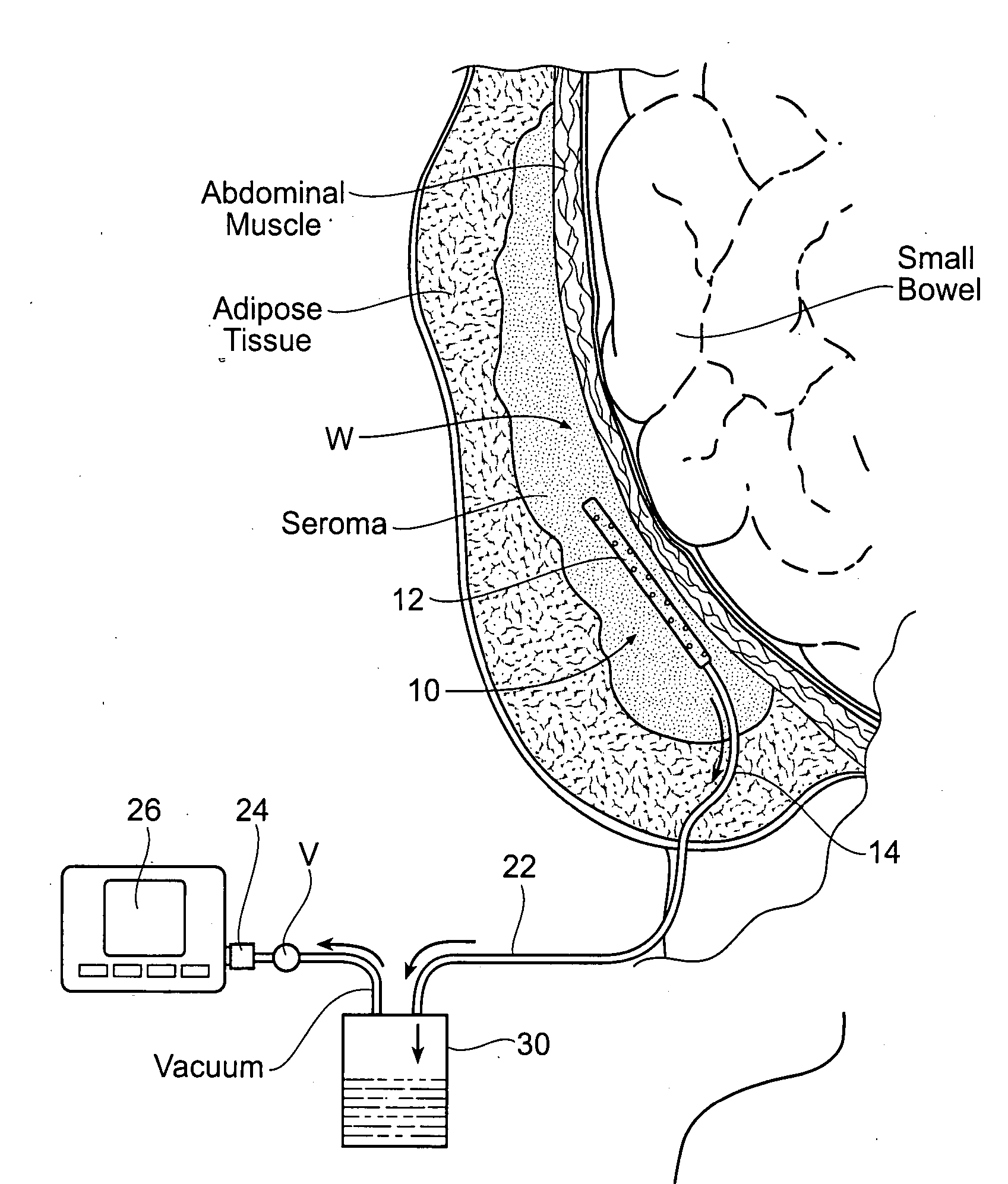
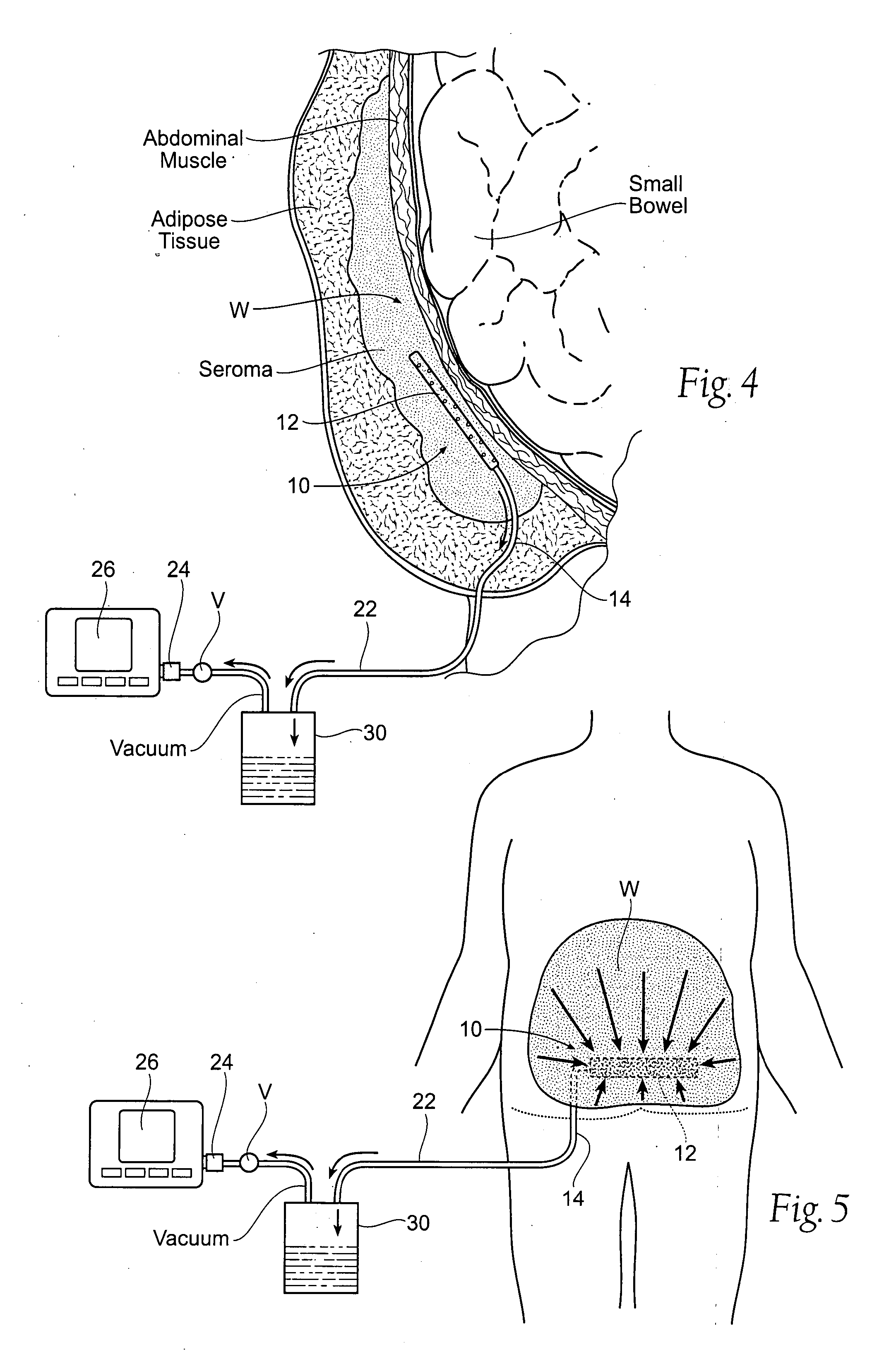
[0039]FIG. 4 shows a wound drainage system 10 comprising an internal drain assembly 12 that is sized and configured for surgical placement within a wound area W (or body cavity). The wound area W may be anywhere in a human or animal, e.g., within a body cavity, or beneath the skin, or in muscle, or within the soft tissues. As will be described in greater detail later (see FIG. 6), the internal drain assembly 12 includes a housing 18 that encloses a foam sponge component 16. The foam sponge component 16 communicates with the wound area W through one or more apertures 20 formed in the housing 18.

[0...


PUM


Abstract

Assemblies, systems, and methods convey fluid from an internal wound site or body cavity by applying negative pressure from a source outside the internal wound site or body cavity through a wound drain assembly that is placed directly inside the internal wound site or body cavity.

Description

RELATED APPLICATION [0001] This application is a continuation-in-part of co-pending U.S. patent application Ser. No. 11 / 646,918, filed Dec. 28, 2006 and entitled Assemblies, Systems, and Methods for Vacuum Assisted Internal Drainage During Wound Healing, which claims the benefit of U.S. Provisional Patent Application Ser. No. 60 / 810,733, filed Jun. 2, 2006, and entitled “Foam Sponge Vacuum Assisted Internal Drainage System,” which are each incorporated herein by reference.FIELD OF THE INVENTION [0002] This application relates generally to the drainage of fluid from the body during the wound healing process, e.g., following surgery, trauma, or placement of implants or surgical devices. BACKGROUND OF THE INVENTION [0003] During surgery, or as a result of trauma, tissue volume can be removed or altered, and an open or dead space is created within the tissue that was previously attached to other tissue. The very small blood vessels that previously ran from the underlying tissue (i.e., m...

Claims


Application Information

Patent Timeline
06 Dec 2007
Publication
US20070282310A1
IPC
A61M27/00
CPC
A61M1/0088; A61M2027/004; A61M27/00; A61M1/916; A61M1/985
Inventors
BENGTSON, BRADLEY P.; MCGUIRE, PATRICIA A.