
Methods to detect cross-contamination between samples contacted with a multi-array substrate

a multi-array substrate and cross-contamination technology, applied in the field of arrays, can solve the problems of inability to reliably and accurately detect the quality of the data obtained in the specific use of bioreactors/fermenters, the method, although quite effective, is tedious and costly,

Inactive Publication Date: 2005-03-03
AGILENT TECH INC
View PDF12 Cites 29 Cited by
  • Summary
  • Abstract
  • Description
  • Claims
  • Application Information

AI Technical Summary

Problems solved by technology

A drawback of strategies that involve contacting more than one sample with a multi-sector array is that cross-contamination may occur between the samples during the time that they are in contact with the array.
As a consequence, the data obtained from that sector may be of inferior quality and may not be reliable.
Such methods, although they are quite effective, are tedious and costly in terms of the number of microarrays used to perform the methods, and the time spent performing the methods and analyzing the results.

Method used


Image

  • Methods to detect cross-contamination between samples contacted with a multi-array substrate
  • Methods to detect cross-contamination between samples contacted with a multi-array substrate

Examples


example 1

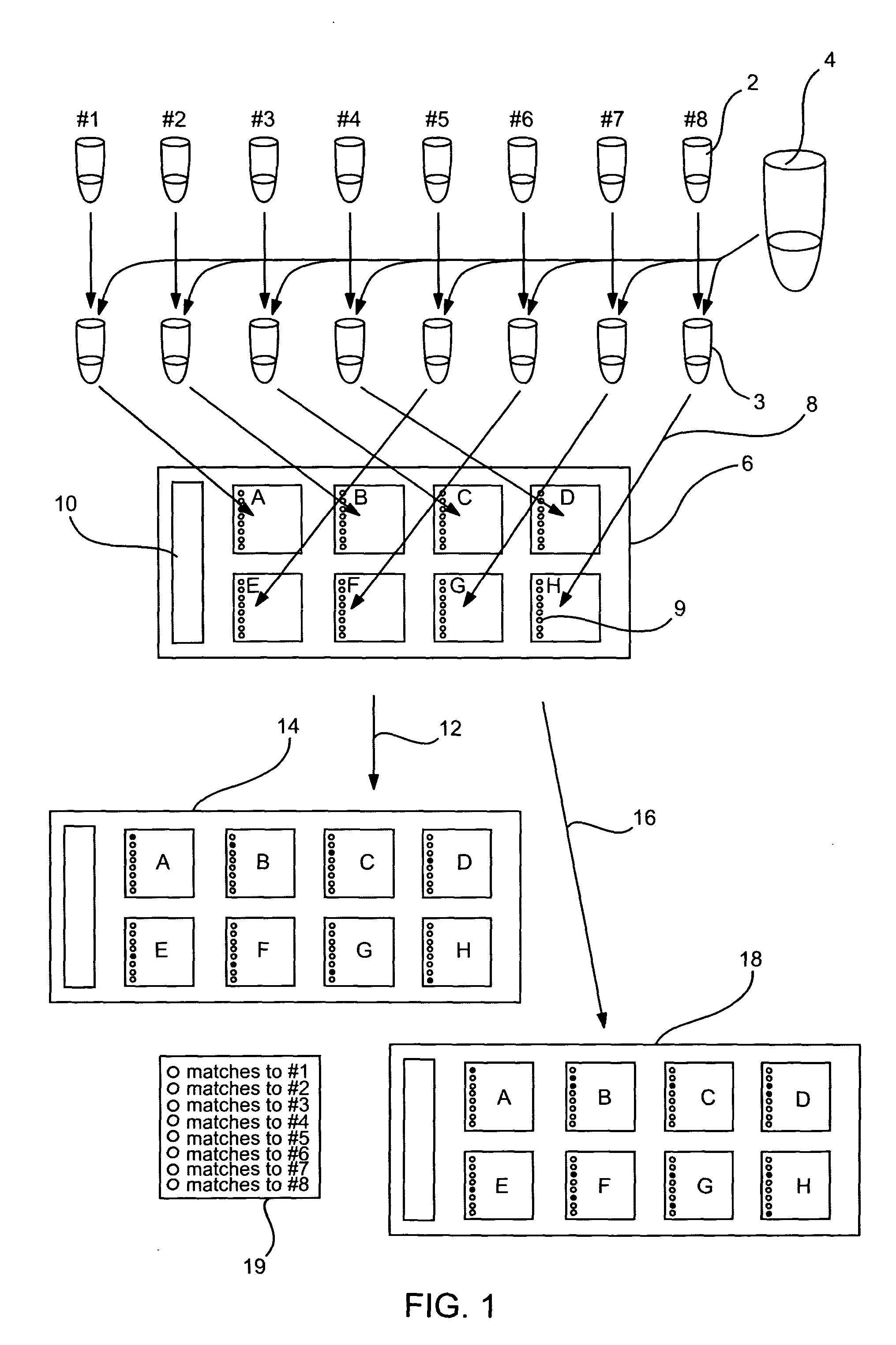
[0136] In the a first method, N, (where N represents the number of arrays of a multi-array substrate, for exemplary purposes N by be 1, 2, up to about 4, up to about 8, up to about 10, up to about 12, up to about 24, 36, 48, 96 or a multiple thereof, e.g., 384 or more), unique spike-in contamination control targets are individually mixed with the hybridization buffer and target of interest. These N aliquots are then dispensed onto the desired probe arrays and hybridized. The N distinguishing contamination control targets are designed to: not cross-hybridize with the targets of interest, not have homology to the other N-1 contamination control targets or probes of interest. For example, for a substrate of eight arrays, N would be 8 and the target preparation method is shown in FIG. 1.

[0137] Each array of the multi-array substrate contains a set of M contamination control probes which are perfect matches to each of the N contamination control targets. M equals N in count, or an integ...

example 2

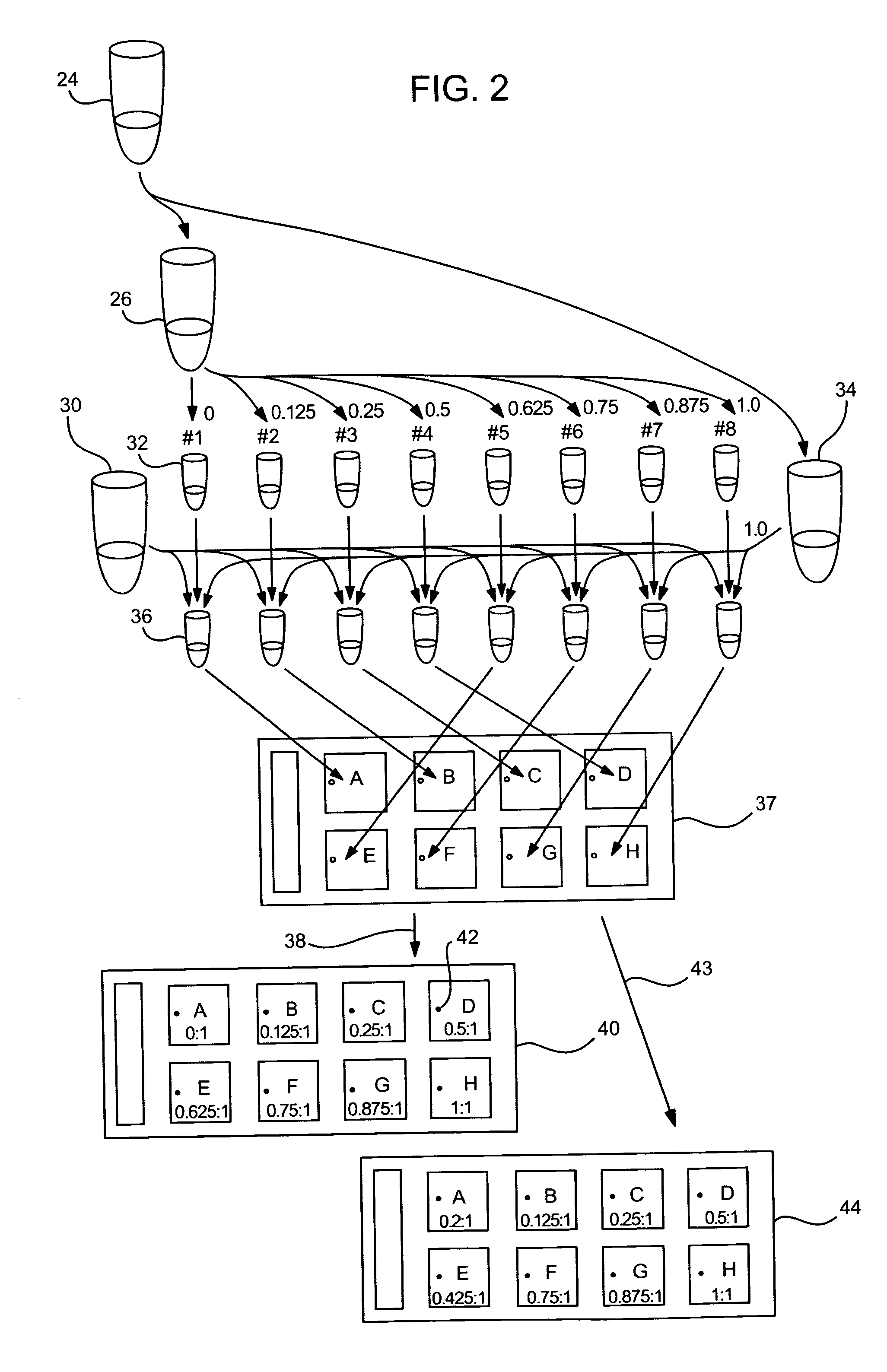
[0139] In a second method, a single spike-in contamination control target is prepared (in tube 24) and two-color labeled to provide the contents of tubes 26 and 34. One color (e.g., green; Cy3) is reserved and used as a reference and the other (e.g., red; Cy5) is successively diluted into N aliquots where the spike-in concentration [x] of each aliquot is [x / N]. In other words, for an substrate of eight arrays, N=8, the spike-in control targets would be prepared in the following concentrations: ⅛, ¼, ⅜, ½, ⅝, ¾, ⅞ and 1x. For example, for an array of eight sub-arrays, where N=8, the target preparation is shown in FIG. 2.

[0140] Each array of a multi-array substrate contains a single contamination control probe which is a perfect match to the contamination control target. When this array of sub-arrays is hybridized, binding of the contamination control probes can be inspected to determine if any cross-contamination occurred during hybridization. In each array, the contamination contro...


PUM

PropertyMeasurementUnit
Compositionaaaaaaaaaa
Concentrationaaaaaaaaaa

Abstract

Methods and compositions for detecting cross-contamination between samples contacted with different arrays of a multi-array substrate are provided. The methods involve contacting sample to arrays of a multi-array substrate that contains cross-contamination probes in each of its arrays, and evaluating the resultant sample contacted arrays for cross-contamination between the samples. In many embodiments, the arrays of the multi-array substrate contain a set of cross-contamination probes for a corresponding set of cross-contamination targets in the sample(s). Kits and systems are provided for performing the invention. The subject methods may be used in a variety of different applications, such as gene expression analysis, DNA sequencing, mutation detection, as well as other genomics and proteomics applications.

Description

FIELD OF THE INVENTION [0001] The field of this invention is arrays, particularly nucleic acid microarrays. BACKGROUND OF THE INVENTION [0002] In nucleic acid sequencing, mutation detection, proteomics, and gene expression analysis, there is a growing emphasis on the use of high density arrays of immobilized nucleic acid or polypeptide probes. Such arrays can be prepared by a variety of approaches, e.g., by depositing biopolymers, for example, cDNAs, oligonucleotides or polypeptides on a suitable surface, or by using photolithographic techniques to synthesize biopolymers directly on a suitable surface. Arrays constructed in this manner are typically formed in a planar area of between about 4-100 mm2, and can have densities of up to several thousand or more distinct array members per cm2. [0003] In use, an array surface is contacted with a labeled sample containing target analytes (usually nucleic acids or proteins) under conditions that promote specific, high-affinity binding of the...

Claims


Application Information

Patent Timeline
IPC IPC(8): C12M1/34C12Q1/68
CPCC12Q1/6837C12Q1/6876C12Q2537/143C12Q2600/166
Inventor FREDRICK, JOSEPH P.TSO, JACQUELINE M.
Owner AGILENT TECH INC
Learn More