
Weight member for a golf club head

a golf club and weight member technology, applied in golf clubs, soldering devices, manufacturing tools, etc., can solve the problems of golf club head body bending, etc., to increase the qualified product ratio and improve the reliability of brazing

Inactive Publication Date: 2005-03-03
FUSHENG IND CO LTD
View PDF6 Cites 74 Cited by
  • Summary
  • Abstract
  • Description
  • Claims
  • Application Information

AI Technical Summary

Benefits of technology

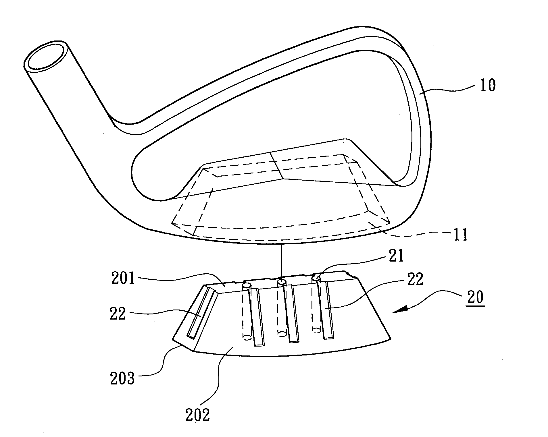
[0007] An object of the present invention is to provide a weight member including at least one compartment for receiving a sufficient amount of a filling material that can be melted and thus fill a gap between the weight member and walls delimiting a recession of a golf club head body, thereby improving reliability of brazing and increasing the qualified product ratio.
[0008] Another object of the present invention is to provide a weight member including at least one compartment for receiving a filling material, allowing the weight member to be positioned in a recession of a golf club head body during brazing. The brazing process is simplified and the operational difficulty of brazing is reduced.
[0009] A further object of the present invention is to provide a weight member including at least one compartment for receiving a filling material and a plurality of channels in at least one of four lateral sides of the weight member. The channels guide and receive the filling material while brazing the weight member into a recession of a golf club head body, thereby increasing the brazing bonding area and improving the bonding strength.
[0010] Still another object of the present invention is to provide a golf club head including a golf club head body and a weight member. The weight member includes a plurality of positioning pegs and a bottom wall of the recession of the golf club head includes a plurality of positioning holes for receiving the positioning pegs. The positioning holes and the positioning pegs are so sized that a gap is defined between the weight member and the bottom wall delimiting the recession during the brazing process, thereby improving the brazing result. SUMMARY OF THE INVENTION
[0011] To achieve the aforementioned objects, the present invention provides a weight member includes at least one compartment for receiving a filling material. The weight member is inserted into a recession of a golf club head body before brazing. The filling material is melted and fills a gap between the weight member and the walls delimiting the recession during the brazing process, thereby improving the bonding strength between the weight member and the walls delimiting the recession of the golf club head body.
[0012] The present invention also provides a golf club head including a golf club head body and a weight member. The weight member includes at least one compartment for receiving a filling material. The weight member is inserted into a recession of the golf club head body before brazing. The filling material is melted and fills a gap between the weight member and the walls delimiting the recession during the brazing process, thereby improving the bonding strength between the weight member and the walls delimiting the recession of the golf club head body.

Problems solved by technology

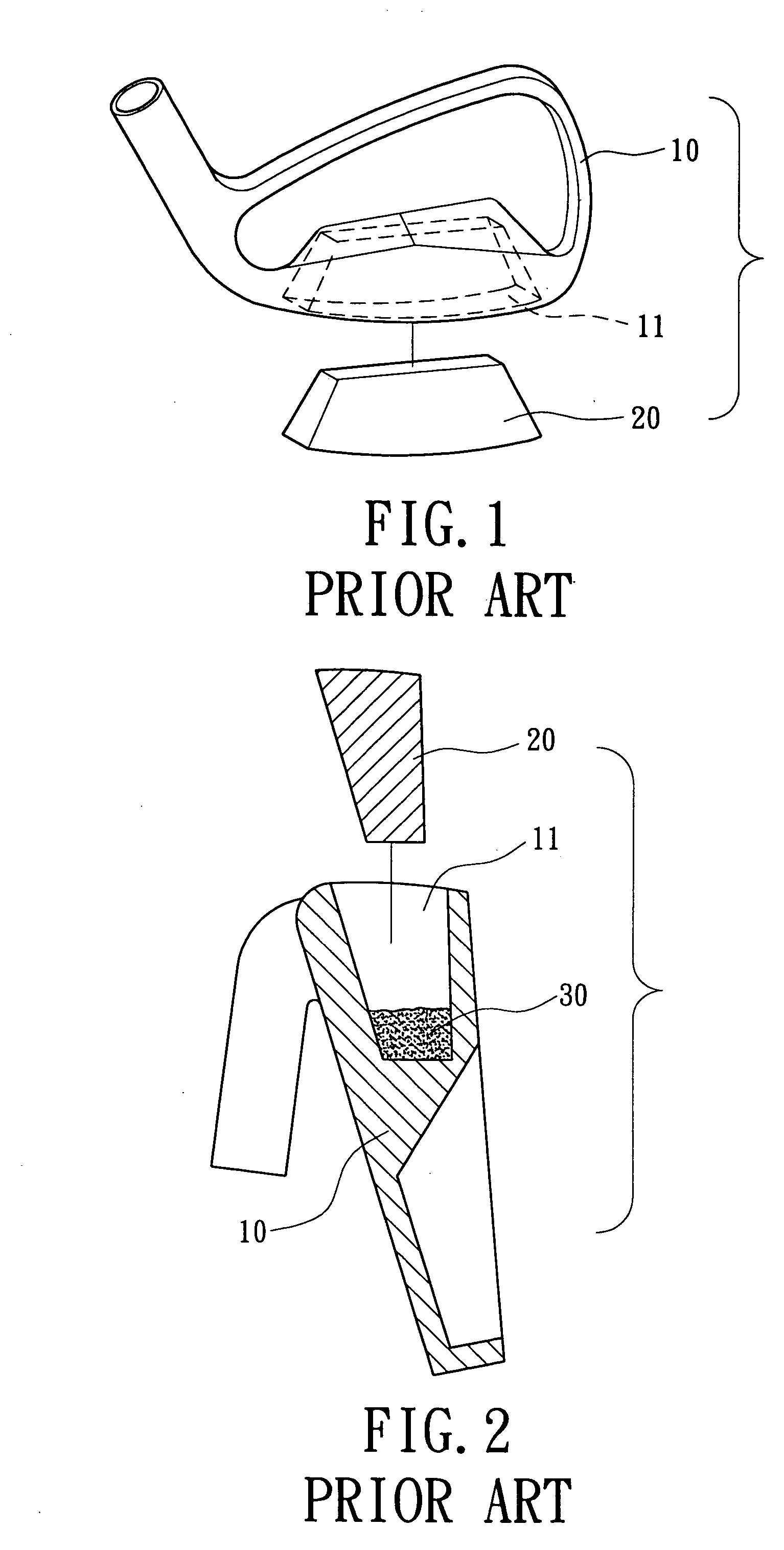
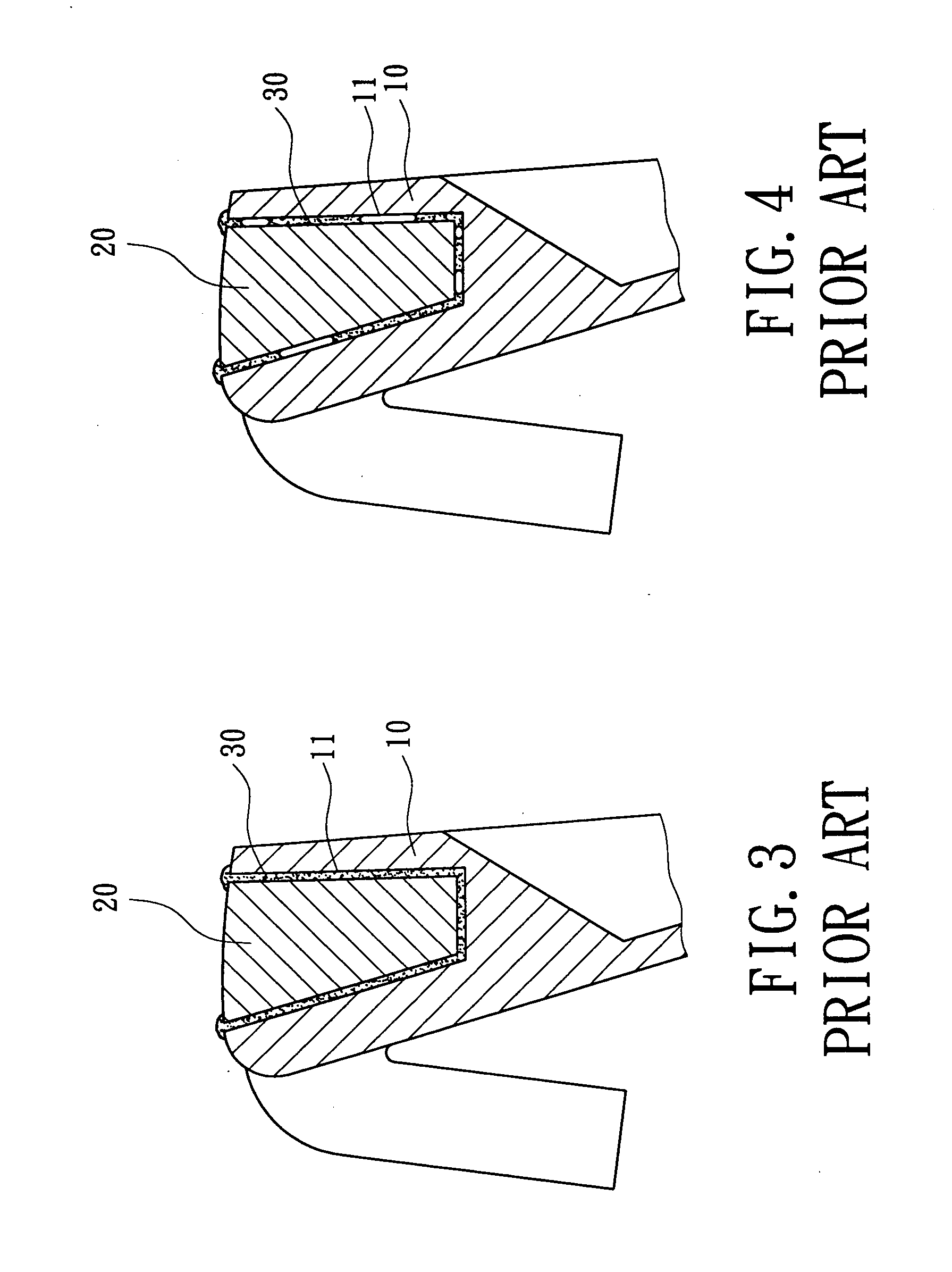
Nevertheless, welding cannot be used to bond the golf club head body 10 and the weight member 20 made of different materials.
Further, if brazing paste is used as the filling material 30, organic materials are generated and volatilize when the brazing paste is heated, adversely affecting the brazing result.
As a result, many problems occur, such as outflow of the filling material 30, unreliable filling of a gap between the weight member 20 and the walls delimiting the recession 11, generation of voids, and waste of filling material.
The bonding strength for the weight member 20 is adversely affected, and the operation of the brazing process is difficult.

Method used


Image

  • Weight member for a golf club head
  • Weight member for a golf club head
  • Weight member for a golf club head

Examples


Embodiment Construction

[0027] Preferred embodiments of the present invention are now to be described hereinafter in detail, in which the same reference numerals are used in the preferred embodiments for the same parts as those in the prior art to avoid redundant description.

[0028]FIG. 5 is an exploded perspective view of a golf club head in accordance with the present invention. FIG. 6 is an exploded sectional view of the golf club head in accordance with the present invention. FIG. 7 is a sectional view of the golf club head in accordance with the present invention during brazing. FIG. 8 is a sectional view of the golf club head in accordance with the present invention after brazing.

[0029] As illustrated in FIG. 5, the golf club head includes a golf club head body 10 and a weight member 20. The golf club head body 10 is made of a low-density metal such as a titanium alloy, Fe—Mn—Al alloy, stainless steel, or soft iron. The golf club head body 10 includes a recession 11 at an appropriate position, and t...


PUM

PropertyMeasurementUnit
depthaaaaaaaaaa
depthaaaaaaaaaa
depthaaaaaaaaaa

Abstract

A golf club head includes a golf club head body and a weight member mounted in a recession of the golf club head body. The weight member includes at least one compartment for receiving a filling material. The weight member is mounted in the recession of the golf club head body before a brazing process for bonding the weight member with the golf club head body. During the brazing process, the filling material is melted and fills a gap between the weight member and walls delimiting the recession of the golf club head body to thereby increasing bonding strength between the weight member and the walls delimiting the recession of the golf club head body.

Description

BACKGROUND OF THE INVENTION [0001] 1. Field of the Invention [0002] The present invention relates to a weight member for a golf club head. In particular, the present invention relates to a weight member having a structure allowing it to be fixed in a recession of a golf club head body by brazing. [0003] 2. Description of Related Art [0004]FIG. 1 of the drawings illustrates a conventional golf club head including a golf club head body 10 and a weight member 20. The golf club head body 10 is made of a low-density material such as a titanium alloy or Fe—Mn—Al alloy, and the weight member 20 is made of a high-density material such as a W—Fe—Ni alloy. The weight member 20 is fixed in a recession 11 of the golf club head body 10 by an appropriate means to form a golf club head product with a lower center of gravity, to increase the overall volume of the golf club head, to reduce the thickness of the golf club head, and to improve the capacity of deformation. Nevertheless, welding cannot b...

Claims


Application Information

Patent Timeline
Patent Type & Authority Applications(United States)
IPC IPC(8): A63B53/04A63B53/06B23K1/00
CPCA63B53/047B23K1/0008A63B2053/0491A63B2053/0433A63B53/0433
Inventor CHEN, CHAN-TUNGTSENG, WEN-HUNG
Owner FUSHENG IND CO LTD
Learn More