Chain tensioner
a chain tensioner and chain technology, applied in the direction of threaded fasteners, bolts, gearing, etc., can solve the problems of insufficient assembly, troublesome and time-consuming assembly, and difficult to operate the chain tension with high accuracy, so as to achieve easy assembly, constant clearance, and accurate operation of the chain tensioner
- Summary
- Abstract
- Description
- Claims
- Application Information
AI Technical Summary
Benefits of technology
Problems solved by technology
Method used
Image
Examples
first embodiment
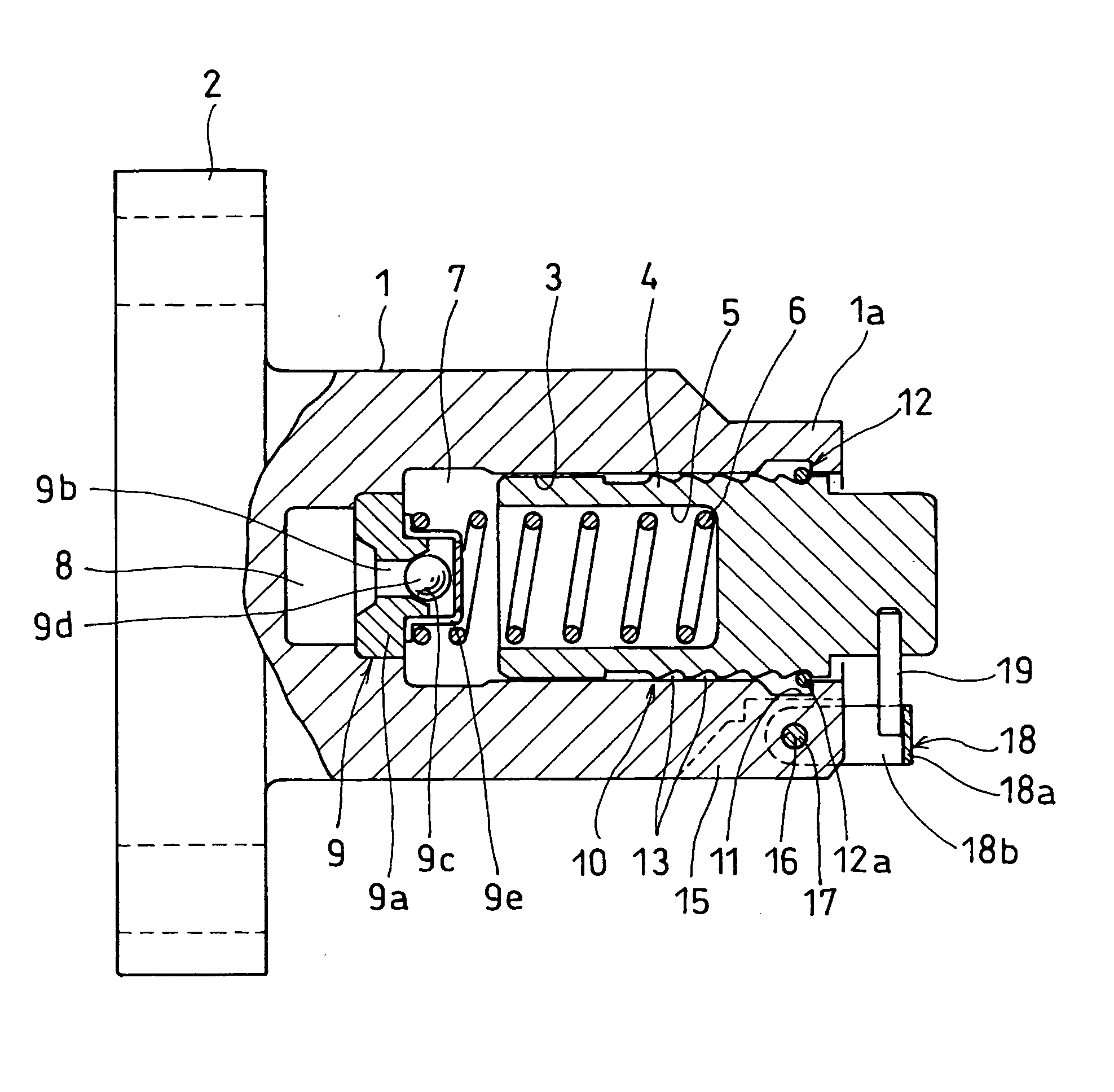
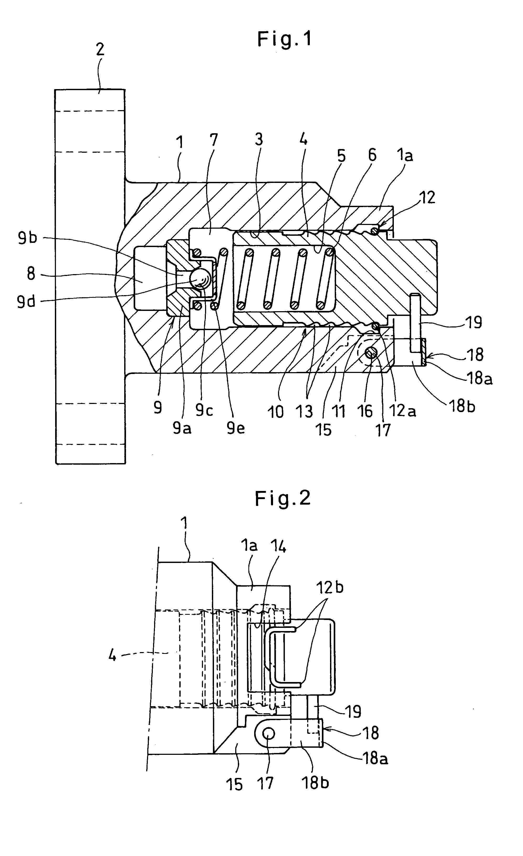
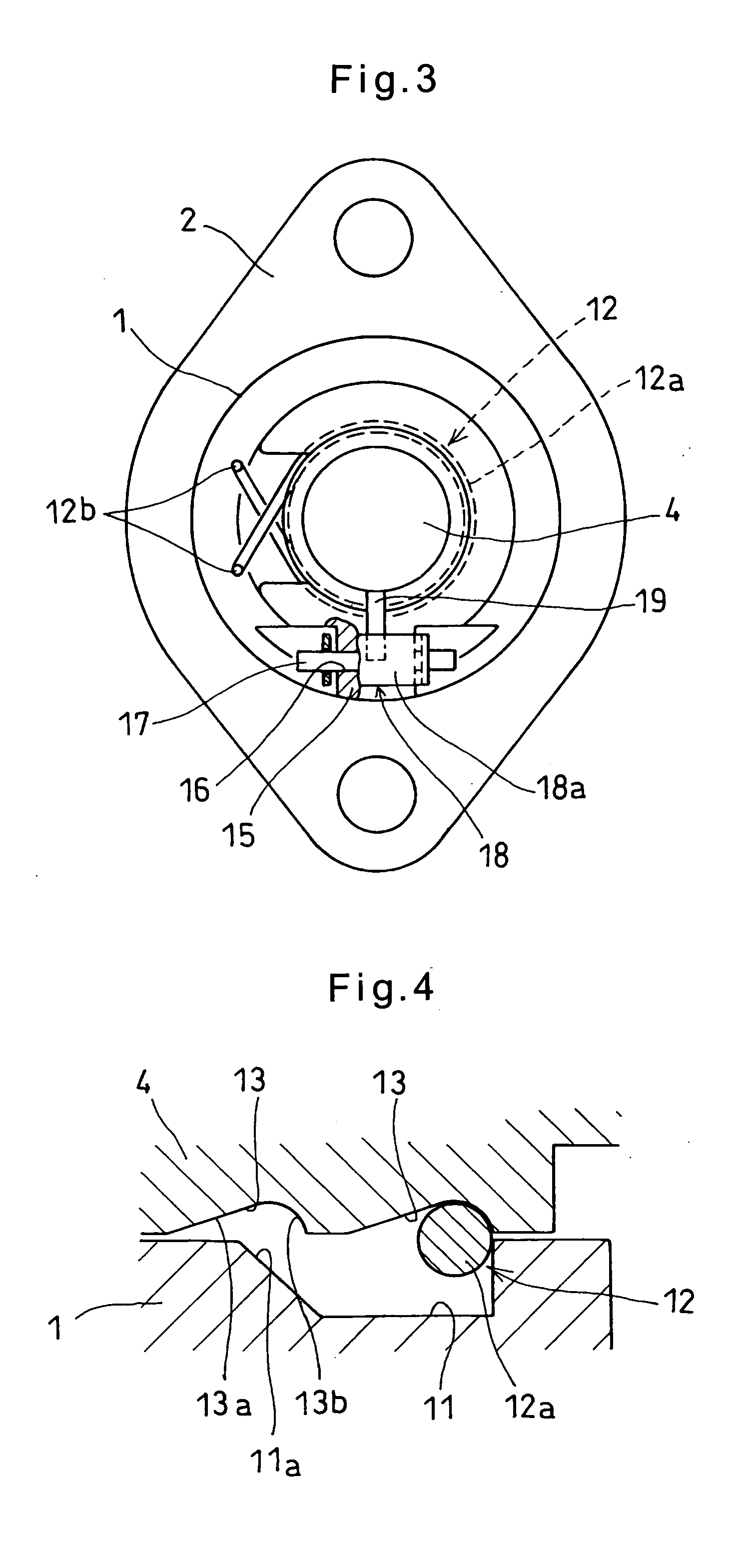
[0038] Referring first to FIGS. 1-4, the chain tensioner of the first embodiment includes a cylindrical housing 1 formed of a soft material such as an aluminum alloy and having a small-diameter portion 1a at a front end thereof and an integral mounting flange 2 at a rear end.
[0039] The housing 1 has a cylinder chamber 3 having an opening at the front end thereof. A plunger 4 is slidably mounted in the cylinder chamber 3.
[0040] The plunger 4 has a spring mounting chamber 5 having an opening at its rear end. A spring 6 is mounted in the spring mounting chamber 5 to bias the plunger 4 outwardly of the housing 1.
[0041] A pressure chamber 7 is defined in the cylinder chamber 3 by the plunger 4. The pressure chamber 7 and the spring mounting chamber 5, which communicates with the pressure chamber 7, are filled with hydraulic oil which is supplied through an oil supply passage 8 formed in the end wall of the cylinder chamber 3. A check valve 9 is provided in the oil supply passage 8 at i...
third embodiment
[0063] In contrast, the locking lever 18 of the third embodiment can move backward in the state of FIG. 9 because the pin 17 is received not in circular holes but in the elongated holes 18c. Thus, the plunger 4 can also move backward in the state of FIG. 9. This prevents the chain 32 from being subjected to excessive tension.
[0064] The fourth embodiment, shown in FIGS. 10 and 11, differs from the first embodiment in that an L-shaped pin 20 is used to keep the plunger 4 pushed into the cylinder chamber 3.
[0065] Specifically, the upper front end of the housing 1 is cut out to define a shoulder 21. A pin hole 22 is formed in the shoulder 21 so as to extend parallel to the axis of the cylinder chamber 3. A through hole 23 is formed in the cylinder 1 in the bottom of the cutout so as to extend to the inner wall defining the cylinder chamber 3. The L-shaped pin 20 has the end of its longer arm inserted in the pin hole 22 and the shorter arm 20a inserted in the through hole 23.
[0066] Oth...
fifth embodiment
[0073] The backward movement restricting arrangement 10 of the fifth embodiment includes a screw rod 27 inserted in a hole 25 formed in the plunger 4 and having an opening at the rear end thereof. The screw rod 27 is formed with a screw thread 28 on its outer surface which is in threaded engagement with a screw thread 26 formed in the inner wall of the hole 25. Each of the screw threads 26 and 28 has a pressure flank F1 which bears the force applied to the plunger 4, and a clearance flank F2. The pressure flank F1 has a greater flank angle than the clearance flank F2, so that the threads 26, 28 have a serration-like longitudinal section as clearly shown in FIG. 12. A spring 6 is mounted between the plunger 4 and the screw rod 27 to bias them away from each other. The threads 26 and 28 have such a lead angle that when the pushing force applied to the plunger disappears, the plunger can move toward and away from the screw rod 27 while turning relative to the screw rod 27 under the for...
PUM
 Abstract
Description
Claims
Application Information
 - R&D
- Intellectual Property
- Life Sciences
- Materials
- Tech Scout
- Unparalleled Data Quality
- Higher Quality Content
- 60% Fewer Hallucinations
Browse by: Latest US Patents, China's latest patents, Technical Efficacy Thesaurus, Application Domain, Technology Topic, Popular Technical Reports.
© 2025 PatSnap. All rights reserved.Legal|Privacy policy|Modern Slavery Act Transparency Statement|Sitemap|About US| Contact US: help@patsnap.com


